SSZTAQ4 october 2016 TPS65983B
The introduction of USB Type-C™ and USB Power Delivery (PD) will forever change the way we interact with our notebooks/tablets/smartphones and accessories A single cable provides both power and data, without any pre-disposition toward which end or device is the host or client. Power can be sourced from both ends or devices and power roles can dynamically change as conditions warrant. With USB PD 2.0 devices hitting the market, we immediately witnessed several uses cases pushing the bounds of what we thought possible.
Figure 1 shows a common configuration of host, hub and peripheral. The intent is to charge the host via the hub while powering both a hard drive and maintaining a lossless image on a monitor. But what happens when you remove the charger plug?
 Figure 1 USB PD Host Powered by USB PD
Hub
Figure 1 USB PD Host Powered by USB PD
HubWell it depends, and that is the issue at hand. In many systems, the power role swap was not quick enough; the data and video connection failed for a brief moment as the USB PD host became the power source. Other systems entered an alternate mode (such as TI’s quick swap) upon the establishment of the original power roles, ensuring that a stable voltage was available even if the charger was removed from the USB PD hub.
 Figure 2 USB PD Hub Powered by USB PD
Host
Figure 2 USB PD Hub Powered by USB PD
HostAlthough designers found a way to solve this problem using USB PD 2.0, it was clear that a common methodology was necessary to provide interoperability and consistency among devices.
The new USB PD 3.0 specification introduces a solution to provide a more consistent user experience across the USB Type-C and USB Power Delivery ecosystem. The original source must recognize that power has been removed and initiate a power role swap. The original sink must apply power to the original source much faster than allowed during a normal PD voltage change. These two components allow the original source to maintain power during a power loss condition.
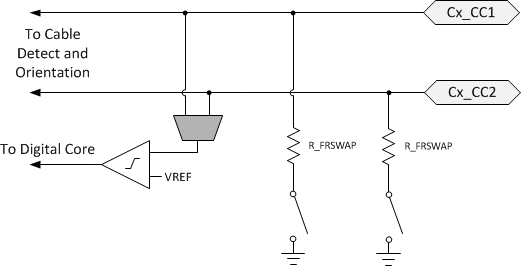
Fast role swap initiates when the source pulls the CC line below 490mV for 60-120µs. Figure 3 shows the signaling components integrated into the TPS65983B. As you can see, a low-resistance pulldown is available on each CC line. When the power has been removed, the TPS65983B internal controller will enable these pulldowns for the appropriate amount of time, signaling to consumers that a fast role swap is about to take place.
 Figure 3 CC Fast Role Swap
Signaling
Figure 3 CC Fast Role Swap
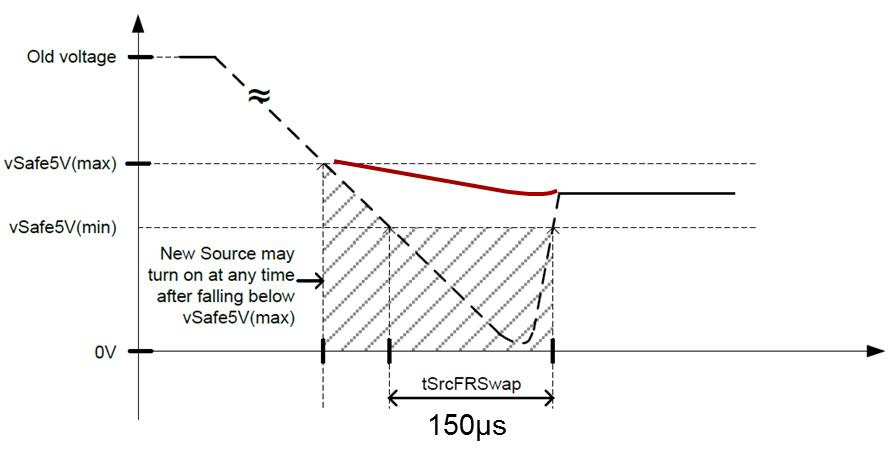
SignalingAfter receipt of the fast role swap message, the host must act very quickly. It has less than 150µs to assume the source role and provide up to 5V at 3A. Under normal conditions and assuming the typical 30mV/µs, the turn-on time for a 5V supply is approximately 158µs. In order to meet the new specification, a much quicker and dynamic solution is required. Fortunately, the TPS65983B integrates both the source and sink power paths. It has the ability to dynamically change the switching time of the internal power FETs to meet the new timing requirements and can dynamically reconfigure the current-limit setting to handle the increased in-rush current caused by the quick turn-on time. Figure 4 below shows the VBUS handoff from the old source to the new source to maintain a constant supply on VBUS.
 Figure 4 VBUS During Fast Role
Swap
Figure 4 VBUS During Fast Role
SwapUSB Type-C and USB PD can now provide the necessary framework to enable to complete the user experience. The TPS65983 not only provides the required USB PD 3.0 signaling, but also includes the power FETs and power-path control to complete the implementation of fast role swap. Proprietary or discrete implementations will no longer be required. With the TPS65983B switching it quick has never been easier.
Additional resources:
- Get more information on USB Type-C ™ products from TI.
- Read blog posts about the need for USB Type-C linear redrivers and how to protect your USB Type-C connector.
- Search for solutions and engage with fellow engineers and TI experts in the TI E2E™ Community USB forum.
- Start your design with the USB Type-C™ and Power Delivery Multiport Adapter Reference Design