SSZTAW5 september 2016 INA240-Q1
As vehicles become more electrified – not just electric vehicles or hybrid-electric vehicles, but even good-old gasoline/diesel power machines – it becomes more critical to accurately monitor the current consumed to ensure performance as well as long-term reliability. One area where this has become vital is in electronic power-steering (EPS) systems.
EPS systems enhance vehicle safety by tailoring variable steering ratios to driver needs, minimizing drive-train interference and potentially modifying the applied torque in safety-critical situations. Driving conditions such as speed can determine the required level of torque and help optimize performance for different driving situations. Consider the different torque requirements required to turn the vehicle when traveling at highway speeds on the German autobahn versus parking at your local grocery store. EPS will provide higher levels of assistance at low speeds than at higher speeds, when it’s not as necessary.
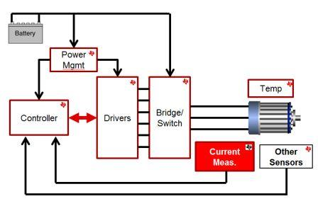
Current measurement is a common requirement across EPS systems. Figure 1 is a high-level block diagram that shows the basics of a typical EPS implementation. I’ll review several types of current sensing implementations for EPS and the advantages of each.
 Figure 1 A Typical EPS System
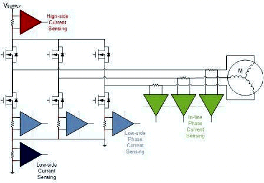
Figure 2 shows four options for current sensing in an EPS system: high-side over-current protection (OCP), low-side OCP, low-side phase current, and in-line phase current. The needs of the system will determine which of the four current-measurement options will be chosen by the system designer. To ensure vehicle safety, it is important to accurately monitor the torque applied to the steering column and translate this into a vehicle response. Precision current measurement ensures the accuracy of this torque detection.
 Figure 2 Circuit Diagram Showing Four
Potential Current-measurement Options for Three-phase Motor
Implementations
Figure 2 Circuit Diagram Showing Four
Potential Current-measurement Options for Three-phase Motor
ImplementationsSystems wanting to achieve maximum performance require precise regulation of the current through the motor to control the motor torque. In-line motor phase current is the only method that will provide continuous phase current, as well as providing the most accurate phase-current representation. However, precisely recreating this in-line phase current presents challenges in selecting an appropriate current sense amplifier for the motor control system. These challenges include the need to identify an amplifier that supports a negative common-mode voltage range to handle the motor’s inductive kickback or to protect the system from a reverse-battery condition. The common-mode voltage at the inputs of the measurement system may be higher than what normal amplifiers can support, as well as having a high dV/dT pulse-width modulated (PWM) nature.
To learn more about the challenges of precise in-line current measurement and how Texas Instruments current-sense amplifiers can help you solve the challenge, see the short, use-case technical documents called TI TechNotes, “Low-Drift, Precision, In-Line Motor Current Measurements with Enhanced PWM Rejection” and “Low-Drift, Low-Side Current Measurements for Three-Phase Systems” for additional EPS system options. In addition, you can check out the Texas Instruments portfolio of current-sense amplifiers.
Additional Resources
- Getting Started with Current Sense Amplifiers video training series.
- Download the “Current Sense Amplifiers” brochure.
- Download the “TI Over-Current Detection Products” brochure.
- Automotive Precision eFuse Reference Design (TIDA-00795).
- Browse current sensing use cases in short, easy-to-read TI TechNotes.