SSZTAX6 september 2016 UCC28722

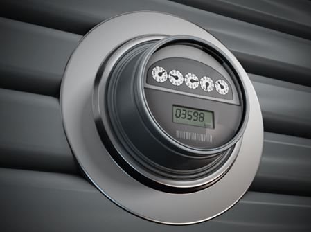
Smart meters are next-generation meters that replace existing meters, which still use technology that was developed decades ago. Smart meters use a secure connection network to automatically and wirelessly send the energy usage to the utility companies. This means that customers will no longer receive estimated energy bills or have meter readers come into their homes to read the meter.
Smart meters use more advanced communication interfaces as compared to conventional IR (Infra-Red) and IrDA (Infra-red Data association) interfaces; they also require more memory and a more powerful microcontroller. These features increase the power consumption which necessitates the use of switch-mode power supply (SMPS) rather than a capacitive-drop power supply. The single-phase energy meter has to operate from minimum 100VAC up to 500VAC. The three-phase energy meter has to operate with minimum of single-phase present (100VAC) up to 300VAC in each of the phases. Compliance with efficiency standards - and more importantly, compliance with lower power-consumption requirements – poses more challenges for SMPS designers as you cannot bill customers for the energy that a meter uses. On the other hand, the smart meter energy usage should not place unacceptable power demands on utilities either.
Tampering is the most important problem that a smart meter power-supply designer has to confront. Most power supplies use ferrite core-based transformers, which are cheap and efficient, but susceptible to strong magnetic fields generated by permanent rare-earth magnets placed a few centimeters away. As soon as the magnet comes near the vicinity of the transformer, it saturates the transformer and creates an over-load condition, damaging the switch (MOSFET/bipolar junction transistor [BJT]), and destroying the power supply. Even if the power-supply controller has an integrated function of protection of transformer core saturation, the power supply will go into protection mode. There will be no power available to the metrology block and thus no metering. However, this is what a meter’s foremost function is. To maintain constant operation during any attempt at tampering, one option is to shield the transformer with a magnetic shield material. But this is an expensive alternative and adds to the assembly cost – as each ferrite transformer would need shielding.
Another option is to use a high-reluctance powdered iron core instead of ferrite. A powdered iron core has a much higher flux density of 1.2-1.4 Tesla, compared to 0.4-0.5 Tesla for ferrite. It costs less than putting a magnetic shield around the transformer, but suffers from higher core loss, which can significantly reduce power-supply efficiency. This drawback may not be particularly significant in smart-meter power supplies, however. Peak power consumption in smart meters jumps to 1W-10W levels, depending upon the wireless communication protocol used. Peak power consumption in smart meters jumps to 1W-10W levels, depending upon the wireless communication protocol used. For sub 1GHz, peak power consumption is around 0.5W; for ZigBee it is around 1W and for Global System for Mobile communication (GSM), it is around 10W.
The meter itself typically consumes less than 1W for most of its operating life, which is governed by the utility’s energy-efficiency regulations. This high light-load efficiency is a main contributor to the average power consumption. Several approaches can increase efficiency at lower/light loads, such as reducing the quiescent amount of the switching controller, using a primary-side controller with a high-voltage startup integrated circuit, or using a switching controller that contains a mixture of frequency and amplitude modulation. The reduction in switching frequency and thus current with the reduction in load reduces core loss, thus justifying the use of powdered iron core transformers.
A high operating voltage is essential in smart meters to protect against the accidental connection of a single-phase meter to two phases (500VAC) or the presence of a 300VAC in each of the three phases of a three-phase meter. But this high voltage increases power complexity, component count and cost.
A flyback topology is the simplest topology for a smart meter power-supply design. In a flyback topology, the switching component has to withstand up to 1000V : 730VDC (300VAC *√3 *√2) plus 220VDC clamp voltage plus 50VDC overshoot due to the snubber diode conduction delay. The switching component should have a voltage rating of 1200V assuming 15% derating. The switching converter (with a built-in 700V/800V MOSFET) uses another 500V MOSFET in cascode configuration to meet the 1200V requirement. Another low-cost technology uses a using a single 1200V BJT with switching controller to take care of high-voltage protection. The cost of BJT with the same voltage and current rating price is one-third the price of a MOSFET.
Thus the optimal SMPS design would feature a powdered iron core-based transformer, control law in switching converter to take care of light-load efficiency and a cascode configuration to handle high-input voltages.
Get started on your smart meter power-supply design by getting to know the UCC28722.
Additional Resources:
- Jump start your design with the Ultra-wide Input Range, Dual Output, Offline AC/DC Bias Supply with PSR Control and BJT Switch Reference Design and Dual-Output 5V at 300mA and 15V at 100mA Isolated Flyback From 85V to 440V AC Mains Reference Design.
- Read the white paper, “Smart power opens door to more efficient electrical use”