SSZTAY4 august 2016 ADC32RF45
**This is the 14th post in an Analog Wire RF sampling blog series. **
In my previous post, I discussed the impact of noise in radio frequency (RF) sampling architectures when receiving small signals to maintain sensitivity. Another determent to receiver performance occurs with large blocker signals. The linearity performance of the RF sampling analog-to-digital converter (ADC) impacts sensitivity when large signals are present. But before we go there, let’s review the linearity measurements.
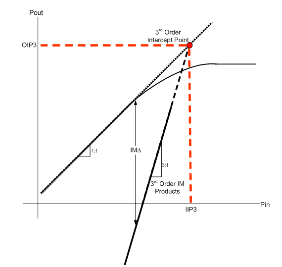
For an ADC, taking linearity measurements related to compression point or saturation power does not make sense, since the output is digital and not analog. Two-tone intermodulation measurements are more relevant. The input third-order intercept point (IIP3) parameter characterizes the device’s linearity performance. Injecting two equal-amplitude tones through a nonlinear system creates intermodulation distortion tones. The IIP3 is the input power in which the third-order intermodulation products are the same amplitude as the fundamental tones. For those not familiar with this type of measurement, the nonlinear behavior of analog components is not intuitive. Figure 1 shows a graphical representation of third-order intercept.
 Figure 1 Graphical Representation of
Third-order Intercept Point
Figure 1 Graphical Representation of
Third-order Intercept PointThird-order intermodulation products are normally at a level well below the amplitude of fundamental tones. Don’t let this fool you. Third-order intermodulation tones increase at a rate of 3-to-1 compared to fundamental tones. The imaginary point at which third-order products “catch up” to fundamental tones is called the intercept point. You cannot actually achieve this condition since the device saturates well before reaching the intercept point. But the intercept point is a good metric for linearity characterization because it is normalized to the input power. In other words, the intercept point is (ideally) the same regardless of the actual input power used in the test. Equations 1 and 2 show the input and output third-order intercept point formulas, respectively.

You transform between the input and output intercept point by simply adjusting for the device gain. All of the system parameters are typically referenced to the input in a receiver, so let’s focus on input intercept-point calculations. Given a device’s intercept point value and input power, you can calculate the amplitude level of the intermodulation signals with Equations 3 and 4:

Equation 4 gives the amplitude of the third-order products. Now let’s look at the frequency location of the products. Equations 5 and 6 show the frequency location of the third-order products given the input frequencies:

A quick way to ascertain the frequency location is to rewrite the equations 5 and 6 as a function of tone spacing. Equations 7, 8 and 9 show the transformation:

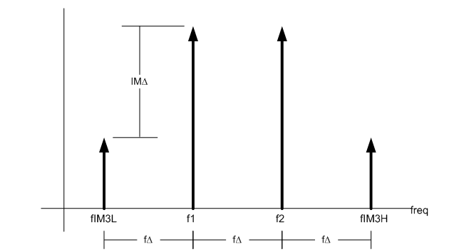
Essentially, the third-order tones reside above and below the fundamental tones by the same spacing as the tones themselves. Figure 2 illustrates the location of the tones.
 Figure 2 Frequency Representation of
Third-order Intermodulation Distortion
Figure 2 Frequency Representation of
Third-order Intermodulation DistortionOther intermodulation orders may also impact system performance; however, the third-order products tend to dominate. The third-order products’ amplitude starts out relatively high compared to higher-order products and the frequency location is close to their generators. Those characteristics, coupled with the 3-to-1 growth slope, make it particularly dangerous in communication systems.
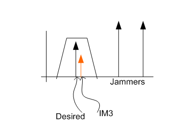
The desired signals are usually small in the receiver. The intermodulation products generated by the desired signals are miniscule and well below the noise floor. Large out-of-band blockers or jammers are the key concern. If these larger blocker signals reside at the proper frequency, they create third-order intermodulation distortion that falls on top of the desired signal, which desensitizes the receiver. Filtering helps knock down any blockers before they get to the input circuitry, but any signals getting through still generate interference. Once interference is present, filtering is not possible since it resides in the same frequency band as the desired signal, as you can see in Figure 3.
 Figure 3 IM3 Desensitizing a
Receiver
Figure 3 IM3 Desensitizing a
ReceiverNoise is the primary system detriment without the presence of blocker signals. When large signals are present, linearity tends to drive receiver sensitivity performance. The game is to optimize the dynamic range of your system to handle the high signals as well as the low signals for optimal performance in all scenarios. RF sampling ADCs like the ADC32RF45 operate with high IIP3 performance as well as low noise to operate in the stringent communications space.
Check back next month, where I will use these new linearity concepts in a real RF sampling receiver system to maintain optimum dynamic range. To make sure you don’t miss my next blog, log in to subscribe to Analog Wire by clicking “subscribe” in the upper right corner of this page.
Additional Resources
- Visit the High Speed Signal Chain University to watch the RF sampling video series.
- Read the white paper, “Direct RF conversion: From vision to reality.”
- Calculating noise figure and third-order intercept in ADCs
- Visit TI’s RF sampling page for a full suite of support resources, including TI Designs reference designs and application notes.
- See other posts in the RF sampling blog series.