SSZTB49 July 2016 TS3A226AE , TS3A26746E , TS5USBA224
For a recent trip to New Orleans, I invested in a quality pair of noise cancelling headphones to help me drown out the chatter. I am thrilled with my new purchase but I’m concerned I won’t be able to use them when mobile phone developers remove the traditional 3.5mm audio jacks from their phones in exchange for using USB Type-C™ connectors. This change will allow for thinner phones and cost savings due to using one less connector.
The USB 3.1 specification supports both charging and data-transfer capabilities, as well as connections to analog audio headsets, by multiplexing four analog audio signals onto pins on the USB Type-C connector. The analog audio signals are the same as those used by traditional 3.5mm headset jacks. This makes it possible to use existing analog headsets with a 3.5mm-to-USB Type-C adapter if the phone will support analog audio. Figure 1 and Table 1 illustrate the pin mappings of a USB Type-C connector that support analog audio.
A simple solution exists that would enable mobile phone designers to easily remove these 3.5mm audio jacks and remain backwards compatible with the existing analog audio signals.
 Figure 1 USB Type-C Connector
Pinout
Figure 1 USB Type-C Connector
Pinout
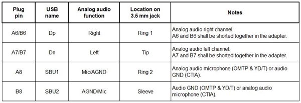 |
The pin mappings in Table 1 look straightforward, but a few challenges will arise when trying to support this type of pinout in your system:
- Analog audio signals have negative voltage swings that can damage the USB physical layer (PHY).
- The USB Type-C connector is reversible.
Analog audio signals traveling through the 3.5mm jack are typically alternating current (AC) signals centered at 0V. The negative voltage portion of the analog audio signal can be damaging to USB PHYs. The best way to resolve this issue is to place a USB and audio switch like the TS5USBA224 on the D+ and D- pins of the USB Type-C connector. As Figure 2 shows, the device can route the analog audio signals to the codec and the USB signals to the USB PHY when appropriate.
 Figure 2 Analog Audio Signal Routing
from USB Type-C Connector
Figure 2 Analog Audio Signal Routing
from USB Type-C ConnectorThe second challenge with supporting the four analog audio signals on a USB Type-C connector is the connector’s reversibility. For the left and right signals on the D+ and D- pins, you can easily accommodate this reversibility feature by shorting the D+/D- pins to their respective D+/D- pins on the top and bottom of the USB Type-C receptacle. Handling the microphone and ground signal on the SBU1 and SBU2 is not as simple as shorting the two pins together. You will need a crosspoint switch like the small TS3A26746E (manual switching) or an audio jack detection crosspoint switch like the TS3A226AE (automatic switching) to route the microphone and ground signals to the codec appropriately.
It is possible to support the same analog audio signals in a 3.5mm jack by solving many of the challenges that arise in multiplexing analog audio signals onto a USB Type-C connector.
Would you like to see more mobile phones remove their 3.5mm jack, but still be able to use your favorite headphones? Log in to comment or visit the TI E2E™ Community Signal Switches forum.
Additional Resources
- Download the TS5USBA224, TS3A26746E and TS3A226AE data sheets.
- Jump-start your design with the USB Type-C Audio Adapter Accessory Mode Reference Design (TIDA-00565).
- See other posts about implementing USB Type-C.
- Learn about TI’s complete portfolio of USB Type-C compliant products and resources.