SSZTBB4 may 2016 UCC28704 , UCC28730

Energy agencies around the world are concerned about growing power consumption and the amount of available deliverable energy. One of the largest demands on the world’s power grid comes from external power supplies (EPSs); these include laptop adapters and phone and tablet USB chargers/adapters. Portable electronics users probably use two to three EPSs every day.
To help conserve energy and reduce waste, these agencies created initiatives and legislation to compel power-supply designers to develop offline power supplies with higher efficiency and lower standby power. The most popular standards for EPSs are the European Code of Conduct (CoC) EPS V5 Tier 2 energy-efficiency standard and the U.S. Department of Energy (DoE) EPS Level VI efficiency standard. The CoC standard is voluntary; however, a majority of power-supply manufacturers in the European Union (EU) are ensuring that their designs meet its requirements anyway. The DoE efficiency standard is mandatory.
Both standards segregate their requirements into power and voltage ranges. In this post, I’ll focus on the low-voltage (<6V) and lower power (<250W) efficiency and standby power requirements.
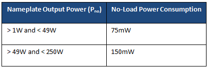
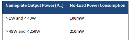
Table 1 and Table 2 list the CoC and DoE standby power requirements for low-voltage/low-power EPSs. You can see that the EU’s voluntary specifications are slightly stricter than the DoE’s mandatory specifications. Designers generally use flyback converters as offline power converters in this power range. The more traditional fixed-frequency pulse-width-modulated (PWM) controllers with higher integrated circuit (IC) standby current would have difficulty meeting either specification. The power dissipation caused by the trickle-charge bootstrap resistor when starting up these older PWM controllers alone could cause the design to fail the standby power requirements.
|
|
To meet these needs PWM manufacturers like Texas Instruments have developed ICs with lower standby current, which enable the use of higher-impedance trickle-charge resistors to reduce standby power (the UCC28704). They have also developed green startup circuitry internal to the PWM controller (the UCC28730) that only dissipates power on initial power up, also reducing standby power.
Plus, primary-side regulated controllers, such as the UCC28704 and UCC28730, regulate the output through the primary to secondary transformer turns ratio and do not require opto-isolator feedback, reducing standby power even further.
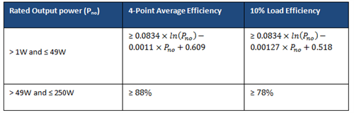
In the past, designers would focus on the maximum load efficiency and not spend much time evaluating overall efficiency. This is mostly because of the power-dissipation and power-density requirements. To help increase EPS overall efficiency, the CoC has specifications for four-point efficiency and 10% load efficiency (Table 3). The average efficiency is based on the average of the efficiencies of the power supply taken at 25, 50, 75 and 100% loads. As I mentioned earlier, the DoE average efficiency standard (Table 4) is not as stringent as the CoC standard, and does not include a 10% load efficiency requirement. The DoE standard does calculate average efficiency at the same load points as the DoE.Please note In Table 1 through 4, the variable Pno stands for the power supply’s nameplate output power. A traditional fixed-frequency flyback converter would have difficulty meeting these efficiency standards, mostly due to switching losses.
|

|
To help meet efficiency requirements in the 1W-25W range, flyback controllers have been designed with FM/AM/FM modulation schemes These controllers modulate the converter’s switching frequency (FM) and primary peak current (AM) in order to control the offline converter’s duty cycle, reducing the power converter’s average switching and conduction losses. To help improve efficiency even further, these controllers use valley switching to reduce switching losses.
In the 25W-250W range, designers generally use quasi-resonant flyback controllers. These controllers are inherently soft switching, with reduced switching losses. Some of these controllers will have burst-mode operation and power-management capability to improve overall efficiency and reduce standby power. One example of power management is to turn off the power factor correction (PFC) pre-regulator at light loading, a feature that some flyback controllers have. PFC is not required below 75W, and turning it off will improve system efficiency below 75W and reduce standby power.
As the world consumes more and more power, being compliant with the EPS V5 Tier 2 and the U.S. (DoE) EPS Level VI efficiency standards becomes imperative. PWM controllers with lower standby current can help reduce stand by power.
Be sure you’re meeting the standards and learn more about TI’s PWM controllers.