SSZTBE6 April 2016 DP83640 , DP83849IF , DP83869HM

Ethernet has propagated from the traditional office environment into a wide range of areas, including harsh industrial environments like factory and building automation. Today, copper cabling is the most common option for Ethernet, but fiber-optic cabling is increasingly finding success in industrial applications because of its long-distance capabilities and electrically isolated interface.
Lost or corrupted packets can pose problems for any network, but they are especially problematic for industrial buses that interconnect processes that must be time synchronized. A corrupted packet is unacceptable for processes with critical timing requirements, but at the very least degrades network efficiency due to the need for packet retransmission.
There are several aspects of the industrial environment that can adversely impact the link signal quality: radiated/conducted emissions; electrical isolation measures; and, link attenuation as the distance between nodes grows. For copper-based networks, these conditions have been addressed by using shielded cabling, magnetics for isolation and constraining link distances. However, these mitigations have placed limits on the deployment of Ethernet in industrial settings. Ethernet over fiber offers a way of addressing these challenges, allowing Ethernet to be deployed deeper into the industrial domain.
| Meet the industry's highest temperature-rated Ethernet PHY | |

|
Learn more about the DP83869HM. The Industry’s only gigabit Ethernet PHY that supports copper and fiber media and enables operation up to 125°C. |
Radiated/conducted Emissions
An industrial environment includes various sources of electromagnetic radiation. Motors, switches, relays and other electrical machinery can generate interfering signals that couple onto copper cabling and cause packet errors. In the worst case, the cable could even be a path that allows high levels of energy to reach the Ethernet physical layer (PHY) transceiver, causing link loss or even damage.
Fiber-optic cabling is immune to electromagnetic interference and does not emit interfering signals. It does not have the electromagnetic properties that cause electrical coupling in copper cabling. Fiber-optic cabling passes light through plastic or glass. There is no generated magnetic field as there may be with copper cabling, nor are fiber-optic cables susceptible to power surges and transient bursts of energy found in industrial environments.
Electrical Isolation
When using copper cabling, point-to-point Ethernet network nodes (transceivers) that are widely spaced must be transformer-coupled to the cable to protect against large differentials in ground potentials. While transformer coupling does provide isolation, there is still an electrical connection between the network nodes.
In a fiber-optic network, there is no electrical connection between the nodes. Therefore, network nodes cannot develop different common-mode voltage levels or common-mode transients on the cabling that could then impact packets. In cases where high voltages pose safety issues, fiber may even be required.
Distance
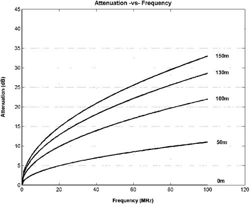
Standard Ethernet is defined by the Institute of Electrical and Electronics Engineers (IEEE) 802.3 specification to work over 100m of copper cabling. While this is a sufficient distance for most applications, there is still a fundamental limit to the distance that the physical copper media can support without packet errors. As shown in Figure 1, the attenuation of Category 5 (CAT 5) cabling at 100m is more than 20 dB, leaving little margin to accommodate signal degradation to either noise or electrical interference.
 Figure 1 Electronic Industries Alliance / Telecommunications Industry Association (EIA/TIA) Attenuation vs. Frequency for CAT 5 Cable
Fiber-optic communication supports much greater distances. Where a copper network might be measured in tens of meters between nodes, a fiber-optic network can be measured in hundreds or thousands of meters. Table 1 lists some of the common Ethernet over fiber standards and their specified cable reaches. In practice, these cable reaches can often be exceeded by a well-designed PHY.
| Fiber standard | Speed | Max distance |
|---|---|---|
| 100BASE-FX | 100 Mbps | 2 km |
| 1000BASE-LX | 1 Gbps | 550 m – 5 km |
| 1000BASE-SX | 1 Gbps | 220 m – 550 m |
For industrial applications, using fiber to support increased distance between nodes may allow repeater nodes to be eliminated, which not only saves cost, but also reduces points of failure, improves determinism for packet timing and reduces end-to-end latency. It can also allow a wider span of control for process controllers, simplifying network architecture.
Ethernet over fiber offers some intriguing advantages for industrial Ethernet that can improve performance in harsh environments, enable spatially broader networks while supporting timing critical processes.
Additional Resources
- Learn more about these TI devices with fiber support:
- Check out these TI Designs reference designs:
- Download these application reports: