SSZTBE9 April 2016 LMH6401
When selecting an amplifier, designers need to understand what distortion components the amplifier will exhibit when stimulated by a signal with two or more closely spaced frequency components. For common linear amplifiers, this distortion is typically represented in the data sheet as intermodulation distortion (IMD) between two test frequencies. However, for radio frequency (RF)-oriented amplifiers such as low-noise amplifiers (LNAs), RF power amplifiers (PAs) and RF gain blocks, an intercept point (IP) spec often represents two-tone distortion, referred to as either the input (IIP) or output (OIP). As linear and RF amplifier speeds blend together in modern high-speed amplifiers such as the LMH6401 variable gain amplifier, it is important to understand how the two specs are related and the manner in which they reflect device performance.
Let’s first look at IMD, because it is
the simpler of the two specs. When the amplifier is stimulated by a two-tone signal
of frequencies  and
and  , it creates harmonic-distortion products at
frequencies
, it creates harmonic-distortion products at
frequencies  ,and also creates
intermodulation products at
,and also creates
intermodulation products at  where
where  is an integer starting at 1. Similar to harmonic
products, the total intermodulation product spectrum is typically dominated by
second- and third-order components because the higher orders are usually
comparatively low in power. (For this reason, I will only focus on discussing the
second- and third-order intermodulation components:
is an integer starting at 1. Similar to harmonic
products, the total intermodulation product spectrum is typically dominated by
second- and third-order components because the higher orders are usually
comparatively low in power. (For this reason, I will only focus on discussing the
second- and third-order intermodulation components: 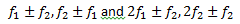 , respectively.) The IMD value is the difference
between the power of one of the input signals (assuming equal power signals) and the
desired intermodulation component. Figure 1 shows the visual relationship of both the harmonic-distortion
and IMD products.
, respectively.) The IMD value is the difference
between the power of one of the input signals (assuming equal power signals) and the
desired intermodulation component. Figure 1 shows the visual relationship of both the harmonic-distortion
and IMD products.
 Figure 1 Intermodulation and
Harmonic-distortion Products
Figure 1 Intermodulation and
Harmonic-distortion ProductsFrom the definition, you can see that IMD is merely the difference in power between a fundamental and an nth-order intermodulation product (IMDn = Pfund – PIMn). From here, you can now understand the relationship between the IMD value and the IP.
The IP value, unlike IMD, is not an actual measurement but a mathematical calculation to obtain a figure of merit that describes system linearity. To understand this, first imagine a slightly nonlinear system with a fundamental power gain of 1 and a two-tone stimulus (the same setup used to measure IMD). Since the system is nonlinear, it will have nth-order intermodulation components that would increase with input power at a ratio of n-to-1. The IP is then defined as the theoretical point at which the nth-order intermodulation product power is equal to the fundamental power.
Figure 2 shows a visual representation of the second- and third-order IPs in relation to the fundamental power, and the respective intermodulation product powers.
") Figure 2 Visual Representation of
Intercept Points (IPs)
Figure 2 Visual Representation of
Intercept Points (IPs)The IPs are only theoretical because a system will reach a maximum-output power point before it should ever reach the actual IPs. From Figure 2, you can see that a more linear system (e.g., a system with lower-power intermodulation products) will “shift” the intermodulation product lines to the right, thus increasing the value of the IPs.
You can easily calculate the nth-order output intercept using Equation 1:
where  is the order of intercept you are calculating,
  is the output power of one fundamental tone and
  is the output power or the
  -order intermodulation product.
This equation can be referred to the
input,  , by subtracting the
gain of the system from the
, by subtracting the
gain of the system from the  value.
Using the commonly calculated third-order output IP as an example, Equation 1 becomes Equation 2:
You know that the third-order
intermodulation distortion (IMD3) value is equal to  , so you can easily rewrite equation 2 as Equation
3:
, so you can easily rewrite equation 2 as Equation
3:
Using the data sheet of the TI LMH6401 high-speed, variable-gain amplifier, you can use the IMD3 and OIP3 spec numbers to verify Equation 3. At 500MHz, the LMH6401 has an OIP3 value of 40dBm and an IMD3 value of 83dBc, both with -2dBm power per output fundamental tone. Plugging these numbers into Equation 3 yields this result:
Accounting for 0.5dB of rounding error, you can see that this calculated OIP3 value matches the value given in the datasheet.
I hope these explanations and examples help you now understand the relationship between IMD and IP and how each can be useful toward understanding a system. IMD is a physical measurement that describes the relative power level of IMD components and is useful when you must know the actual power of various components. IP is useful as a figure or merit for the linearity of a system, but does not immediately relate any exact measurement values. Understanding both specifications allows you to have the best understanding of system performance related to two-tone distortion.
Have you ever confused IMD and IP before? What type of issues did it cause in your design? Log in below and leave a comment.
Additional Resources
- Learn more about TI’s high-speed amplifier portfolio and find more technical resources.
- Download the LMH6401 data sheet.
- Read other high-speed amplifier blog posts.
- Learn about TI’s entire portfolio of amplifier ICs and find technical resources.