SSZTBJ1 March 2016 LM1084
Output stability is a key concern for any power-supply design. Given the simple nature of linear regulators (most of which have only three pins), it can be easy to forget its importance. While many techniques exist to ensure a stable output, the easiest and most cost-effective solution is to add or use the equivalent series resistance (ESR) of the output capacitor.
For demonstration purposes, let’s use the LM1084 low dropout positive regulator with a 5V output. The LM1084 is capable of providing 5A of current to the load, which is useful when large current spikes may be present. It is also a quasi-LDO, meaning that the pass transistor is a single NPN transistor driven by a PNP transistor, as shown in Figure 1. Because of its internal structure, quasi-LDOs generally need some amount of ESR at the output capacitor to ensure stability.
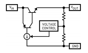 Figure 1 Quasi-LDO Simplified Internal
Schematic
Figure 1 Quasi-LDO Simplified Internal
SchematicGenerally, the ESR of tantalum and electrolytic capacitors is enough to provide stability, but as designs become more space-constrained, ceramic capacitors are preferable due to their smaller size. Since ceramic capacitors have virtually no ESR, adding an external resistor in series mimics the behavior. In this blog, I’ll use the LM1084 to demonstrate how to estimate the optimal ESR value at the output and test its effectiveness in the lab.
Methods for Testing Stability
One traditional method when testing for stability is to use a frequency response network analyzer, which injects a small sinusoidal signal into the feedback loop and measures the gain and phase response across frequency. It requires breaking the feedback loop, so you generally cannot test fixed-output regulators with the feedback loop built into the integrated circuit (IC). This method is more tedious to set up, requires extra lab equipment, and can result in errors if you don’t take the proper precautions.
A simpler method is to perform a load-transient test and observe the ringing at the output. Figure 2 shows an example setup that can provide a 50mA to 1A load transient with a 5V regulator output. The function generator provides a square wave to the gate of the N-channel FET. When the N-channel FET is driven, the total load resistance is effectively 5Ω. When the NFET is not driven, the load resistance is 100Ω, which is just enough resistance to satisfy the minimum load requirement.
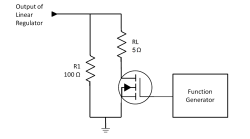 Figure 2 Load-transient Test
Setup
Figure 2 Load-transient Test
SetupObserving the Output Ringing
The ringing at the output during a load transient can help determine if the regulator is stable. Figure 3 shows the schematic of the LM1084 with a ceramic output capacitor and no external ESR added. Figure 4 shows its load-transient response. As shown in Figure 4, there is an excessive amount of ringing, which you can damp by adding some ESR to the output capacitor. But how much ESR should you add?
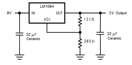 Figure 3 LM1084 Schematic – No
ESR
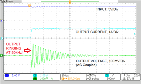 Figure 4 Load-transient Response – No ESR
Calculating the ESR Value
You can determine the appropriate ESR value with Equation 1:
This equation will give you a minimum ESR that provides a zero at the output ringing, or oscillation, frequency. During a load-transient test, the output ringing frequency gives you a clue that the 0db crossing point is near that frequency, and therefore needs a bit of phase boost to dampen the output response. Providing a zero at that frequency will provide the phase boost you need. Let’s do a calculation using the examples in Figure 3 and Figure 4.
The oscillation frequency in Figure 4 is about 50kHz and the output ceramic capacitor is 22μF. Plugging those numbers into Equation 1 gives you a minimum ESR value of 145mΩ:
Now let’s see the effect of adding 145mΩ of ESR to the output response during a load transient. Figure 5 shows the schematic with ESR added, while Figure 6 shows its load-transient response. Although the ringing was eliminated, the side effect is that the effective output capacitance diminishes with the addition of ESR, and the capacitor becomes just a bit more resistive. This means that the initial output dip is larger.
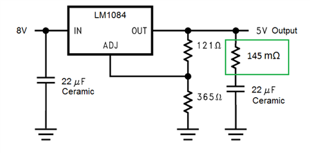 Figure 5 LM1084 Schematic – with
ESR
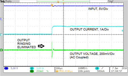 Figure 6 Load-transient Response – with
ESR
Figure 6 Load-transient Response – with
ESRIn summary, you can dampen the output ringing produced by linear regulators by simply adding an external resistor, which is especially useful when designing with ceramic capacitors. The calculation is simple and requires minimal equipment to test and verify stability.
Additional Resources
- Read the “ESR, Stability, and the LDO Regulator” application note to understand why higher ESR capacitors are necessary, how to choose them, and how to determine whether or not the regulator is stable.
- Download the “Linear Regulators: Theory of Operation and Compensation” application note that discusses the operation and compensation of linear regulators.