SSZTBL0 february 2016 LM3421 , LM3423 , LM3424 , LM3429 , TPS92691
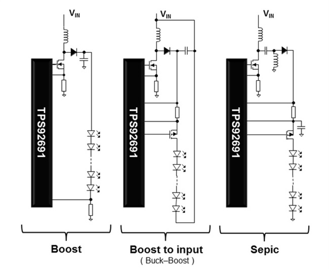
In my last two blog posts, I described a common DC/DC topology in LED drivers – buck or step-down regulators. In this post, I am going to talk about some other DC/DC topologies that are also common in driving LEDs – boost converters, boost-to-input converters and single-ended primary inductor converters (SEPICs), as seen in Figure 1. A boost converter provides an output voltage that is always higher than the input voltage. A boost-to-input converter has a construct similar to a boost converter, with the load connected across the converter output and the input port. A SEPIC provides an output voltage with respect to ground that can be either lower or higher than the input voltage. SEPICs consist of a coupled inductor and a capacitor instead of a single inductor like boost or boost-to-input converters.
 Figure 1 DC/DC Converter Topologies for
Boost Converter, Boost-to-input Converter and SEPIC
Figure 1 DC/DC Converter Topologies for
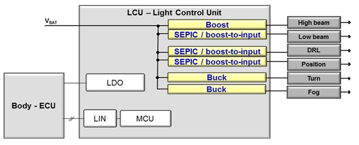
Boost Converter, Boost-to-input Converter and SEPICYou may wonder what kinds of applications require these topologies: a popular one is LED headlights. A typical automotive LED headlight control unit block diagram is being shown in Figure 2. More and more vehicles on the road have LEDs rather than traditional incandescent or high-intensity discharge lamps. LEDs last longer and the DC/DC LED driving circuit provides better system efficiency.
There are other reasons to use these topologies. One reason is that an LED’s flexible voltage (or the number of LEDs) enables headlight functions which include high beam, low beam, daytime running light (DRL) and fog. Another reason is that the car battery is usually not sitting at a fixed voltage level. In extreme conditions such as cold crank, warm crank and load dump, the car battery provides a voltage range from below 6V to over 40V. With such a large range of input voltage to drive the LEDs, a natural choice would be either a boost-to-input converter or a SEPIC. Of course, if the LED voltage is always higher than 40V (over the whole input voltage range provided by the car battery), a boost converter would be the best choice.
 Figure 2 Block Diagram of a Typical
Automotive LED Headlight Control Unit
Figure 2 Block Diagram of a Typical
Automotive LED Headlight Control UnitA common approach to build these types of converters is to use a low-side N-channel FET controller, such as the LM3421, LM3423, LM3424 or LM3429. TI’s newly released TPS92691 is configurable as a boost converter, a boost-to-input converter or a SEPIC. With an independent analog current-adjustment input pin and a pulse width modulated (PWM)-dimming input pin, the converter is capable of providing a 1,000-to-1 contrast ratio in combining both pins’ input. The TPS92691 has a rail-to-rail current-sense amplifier that provides flexibility for either a high-side current-sense resistor or a low-side one. It can also regulate an average LED current with +/-3% accuracy at room temperature for an output LED voltage level as low as 2V or as high as 60V.
Thanks to the DC/DC power conversion topologies described above, we are now able to drive a car with cool LED headlights that provide precise brightness control, environmental friendly and converts power in a highly efficient manner.
Additional Resources:
- Read other blogs on LED lighting.
- Jump start your lighting design with the Dimmable LED Driver Reference Design for Aftermarket Light Bars, Spot Lights, and Flood Lights.
- Discover what’s new with LED lighting illumination on TI.com.
- Check out a reference design PMP7759 that shows the boost-to-input concept.