SSZTBY3 november 2015 TMS320F28035
Hybrid electric vehicle (HEV) and electric vehicle (EV) power electronics are designed to provide power flow from high-voltage batteries (400 V/600 V) to low-voltage batteries (12 V) in normal operating mode. In addition, these automotive power electronics must be capable of bi-directional DC/DC conversion to provide power flow from a low-voltage battery to a high-voltage battery during emergency situations, where the HEV/EV needs a boost at start-up. In other words, the bi-directional design will need a buck mode to step the voltage down and a boost mode to step the voltage back up.
Design Considerations
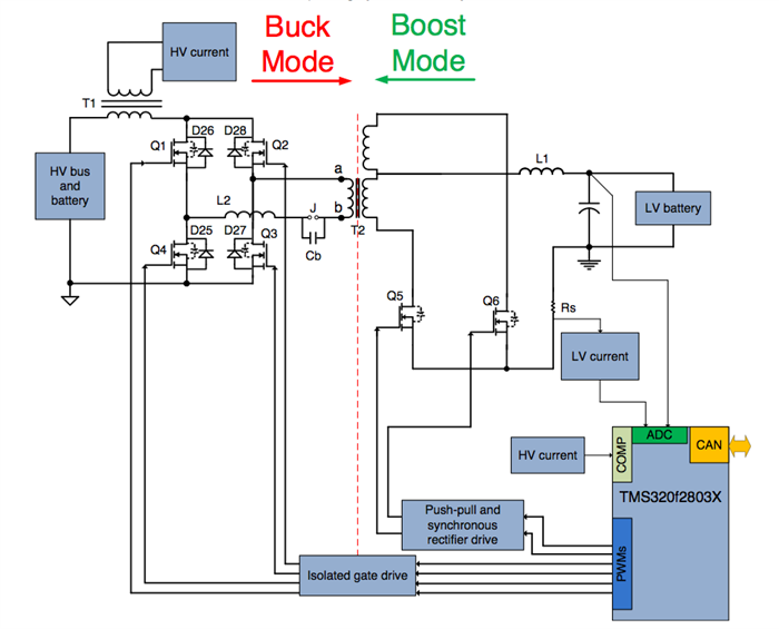
An ideal topology for the buck mode converter stage (400 V to 12 V) is a phase-shifted full bridge (PSFB). This topology allows for zero-voltage switching (ZVS) of the four electronic switches on the primary side of the isolation transformer and of the diode rectifiers (or MOSFET switches) on the secondary side, resulting in lower switching losses. In order to achieve the best performance for low-output voltage and/or high-output current ratings, synchronous rectification is required on the secondary side to remove diode rectification loss.
Various modes of operation can be leveraged to control the PSFB power stage, such as voltage mode control (VMC), average current mode control (ACMC) or peak current mode control (PCMC). In order to avoid redesigning the control circuit with changes to the power stage sensing circuitry, it is best to consider using a high-performance digital microcontroller.
TI’s C2000™ 32-bit microcontrollers (MCUs) are designed specifically for digital power applications. The C2000 Piccolo™ TMS320F28035 MCU contains enough CPU processing power to run advanced control algorithms, while also including flexible PWMs for advanced switching patterns.
For the boost mode converter stage, synchronous rectifier switches can be leveraged as push-pull switches. The buck mode inductor can act as a current source in this mode, letting this topology work as a current-fed push-pull converter.
These control algorithms can be implemented on a single C2000 TMS320F2803x MCU. The TMS320F2803x MCU interacts with the power stage by way of feedback signals and PWM outputs, and can be placed on the low-voltage side.
Available TI Design with Full Software and Schematics
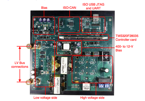
The bi-directional 400 V - 12 V DC/DC converter TI Design implements the approach described above. Four MOSFET switches (Q1 to Q4) form a full bridge on the high-voltage side of the isolation transformer, while two MOSFET switches (Q5 and Q6) live on the center-tapped low-voltage side. These switches work as synchronous rectifiers in buck mode and as push-pull switches in boost mode.
Controlling this system in different operation modes requires complex PWM waveforms and requires fast closed-loop calculations. This implementation leverages the features on the TMS320F2803x MCU such as advanced PWM peripherals, a high speed 12-bit ADC, and integrated analog comparators with DAC and slope compensation.
System features include:
- 200-VDC to 400-VDC HV bus voltage range
- 9-VDC to 13.5-VDC LV bus voltage range
- 300-W rated output operation in either direction
- 33-A rated current on the LV bus and 1.8-V rated current on HV bus
- Seamless on-the-fly transitions between buck and boost modes
- Phase-shifted full bridge operation in buck mode
- Current-fed push pull operation in boost mode
- 100-KHz PWM switching
- VMC and ACMC of output inductor current
- Multiple SR switching schemes
- Fault Protection: overcurrent, undervoltage, overvoltage
Start designing with the bi-directional DC/DC converter today.