SSZTC47 september 2015 ISO7520C , UCC27324 , UCC27714

In a typical close-loop power-electronics system, the gate driver is the key interface between the control system (normally a low voltage like 12V) and the main power stage (normally a high voltage like 400VDC). The gate driver’s purpose is to translate the input low-voltage control pulse signal to the power transistor (MOSFETs, IGBTs) in a clean, robust and timely manner.
In this blog series, I’ll take a look at two ways to drive high-voltage transistors: the gate-drive transformer and the high-voltage driver IC, and illustrate the strengths and weaknesses of each.
The key specifications defining the performance of the gate driver are:
- Static characteristics: functional voltages (VCC/DD, bootstrap function), peak source/sink current and UVLO.
- Dynamic characteristics: propagation delay, delay matching, pulse-width distortion, common-mode transient immunity (dv/dt) and rising/falling time.
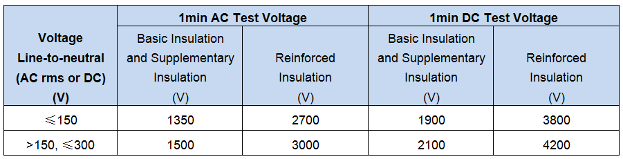
You will also need to consider safety standards and compliance – protecting human operators from hazardous voltage/currents higher than 42.4Vpk AC or 60VDC. For example, in cellphone chargers, the low-voltage DC output is insulated from the universal AC input (85~265VAC) where double or reinforced insulation is necessary to eliminate the need for a grounded metal enclosure as well as a grounded power plug. Table 1 shows the test voltages requirement (IEC 61010-1 ed. 3.0) for solid insulation in the main circuits of Overvoltage Category II up to 300V.
|
Figure 1 is a simplified circuit diagram with the controller sitting on the secondary side (secondary-side control). The main power-stage insulation is based on a conventional power transformer. You can use two major types of gate drivers to transmit the gate-drive signals with insulation between feedback control in the secondary-side and primary-side gate driver:
- A gate-drive transformer (see Figure 2[a]) with insulation by magnetic coupling.
- A high- and low-side gate driver with signal-isolator interface (see Figure 2[b]). The signal isolator interface could be an optocoupler (optocoupling) or digital isolator (magnetic or capacitive coupling).
 Figure 1 Simplified Circuit Diagram
with Secondary-side Control
Figure 1 Simplified Circuit Diagram
with Secondary-side ControlThe gate-drive transformer can deliver both the logic gate-drive signal and required gate driver required peak current/power capability.
A high- and low-side gate driver uses a signal isolator interface to provide the required insulation and uses gate-driver ICs to provide enough gate-drive power/current capability.
 Gate Drive Transformer (b) High and Low Side Driver + Isolator") Figure 2 Simplified Circuit Diagrams
(a) Gate Drive Transformer (b) High and Low Side Driver + Isolator
Figure 2 Simplified Circuit Diagrams
(a) Gate Drive Transformer (b) High and Low Side Driver + IsolatorTable 2 lists the key components required for each implementation. A gate-drive transformer uses the UCC27324 as the low-side driver with two-channel Ipk=±4A capability to drive the gate-drive transformer and the GA3550 from Coilcraft with reinforced insulation. A high- and low-side gate driver plus isolator uses the ISO7520C dual-channel digital isolator to provide reinforced isolation, the UCC27714 as the high- and low-side gate driver, and Vishay MURS360 as the bootstrap diode.
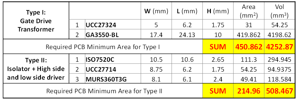
Take a look at about the total required PCB minimum area in Table 2: Type II (a high- and low-side driver plus isolator) takes only 215mm2, and will save over 50% of PCB space over type I. And the volume savings will be more significant considering the awkward height of the reinforced insulation gate-drive transformer.
Moreover, this calculation is only counting the major components. When considering the signal conditioning circuit, the savings of Type II over Type I will increase.
Stay tuned for the next installment of this series, when I’ll discuss the strengths and weaknesses of each driver.
Additional Resources
- Check out TI’s new high-speed, 600V high-side low-side gate driver with 4A peak output.
- Check out detailed safety considerations in this paper from IEEE “Safety Considerations in Power Supply Design”