SSZTCI1 july 2015 INA226 , INA250 , INA282 , INA284 , INA286 , INA300
In parts one and two of this series, I discussed concepts related to specifications of current-sense amplifiers and how to use the application requirements to narrow device selection. In this installment, I’ll discuss how the current range helps derive the shunt-resistor value, as well as how the current range and shunt value combined with device performance drive a trade-off between accuracy and power dissipation.
Until the recent release of TI’s INA250 current-sense amplifier (more on this later), the current didn’t actually pass through the current-sense amplifier. Therefore, the current range being measured didn’t directly dictate the device specifications.
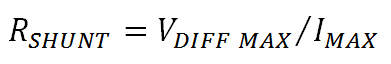
For an analog output current-sense amplifier, the maximum current range combined with the full-scale input (maximum differential input voltage) will derive the ideal shunt resistor value, as shown in Equation 1:
If you look at most current-shunt monitor data sheets, you’ll notice that the maximum differential voltage isn’t specified; rather, a maximum output voltage swing is specified. You’ll want to match this to the full-scale input range of the next link in the signal chain. To maximize performance, you’ll want the maximum-output voltage swing to be greater than the next link’s full-scale input range. Typically, the maximum output swing is a function of the supply voltage supplied to the current-sense amplifier. For example, with the INA282, the output-swing range is defined as 0.4V below the supply voltage to 0.04V above the voltage on the ground pin, as shown on page 6 of the datasheet.
 Figure 1 Electrical Characteristics of
the INA82 Current-sense Amplifier
Figure 1 Electrical Characteristics of
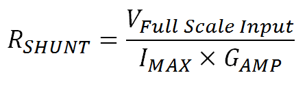
the INA82 Current-sense AmplifierIf you use the full-scale input range as the desired output swing of the current-shunt amplifier with maximum current flow, then you can modify the shunt-resistor equation, taking into account the gain (GAMP) of the current-sense amplifier. Equation 2 shows this modification.
Let’s look at two examples of how to use this equation. For both examples, we will use the maximum current as 5A and the full-scale input of the next link in the signal chain as 2.5V. Let’s consider using either the INA286 (gain of 100V/V) or INA284 (gain of 500V/V).
 Figure 2 INA286 and INA284 gain and ideal RSHUNT
value with a maximum current of 5A and a full-scale input of 2.5V
Figure 2 INA286 and INA284 gain and ideal RSHUNT
value with a maximum current of 5A and a full-scale input of 2.5V The ideal RSHUNT value may not be readily available, so you may have to choose the closest value – which may be is less than ideal. The reason you need to choose a resistor that is of a lesser ohmic value than the ideal is to keep the voltage input to the next link below the full-scale input level.
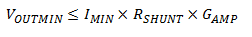
Using Equation 3, you will also need to verify that the minimum current value creates an output voltage from the current-shunt amplifier that is above the minimum output voltage.
Looking back at these two examples, you can calculate the minimum current for each solution as 80mA.
The next question is what to do with the fact that I have just calculated multiple options for different combinations of shunt value and amplifier gain. The answer comes down to a trade-off between the desired accuracy of the application versus the power dissipated in the shunt resistor. While I have not delved into accuracy yet, I will cover this in part 4 of this series; briefly, the larger the value of RSHUNT, the higher the accuracy. However, as shown in Figure 3, the higher values of RSHUNT lead to an increase in the power dissipated by the shunt resistor and adds to the overall load of the system.

You’ll need to look at various current-sense amplifier options for gain and offset voltage and calculate how those options combined with the current range will affect the shunt-resistor value, achievable accuracy and power dissipation.
Most digital-output devices, such as the INA226, specify a full-scale shunt-voltage input range. This simplifies the calculations in many cases because there is not an additional gain stage to trade off against. The shunt value is simply the closest-available value resistor found by dividing the device’s maximum-input voltage by the maximum current.
I mentioned briefly the brand-new INA250 current-sense amplifier. By integrating the shunt resistor, the INA250 can support a maximum current level based on the heat generated by the current flowing through the shunt. Look for more information in future blog posts about how the INA250 is redefining precision current measurement.
In the next installment, I will address the basics of accuracy and how device selection affects accuracy.
Additional Resources
- Learn more about TI’s broad current-sense portfolio.
- Watch this video about how the INA300 is optimizing overcurrent detection.
- Learn from online training about getting started with current-sense amplifiers.
- Check out these related TI Designs reference designs: