TIDT274 April   2022


  1.   Description
  2.   Features
  3.   Applications
  4. 1Test Prerequisites
    1. 1.1 Voltage and Current Requirements
    2. 1.2 Considerations
    3. 1.3 Dimensions
  5. 2Testing and Results
    1. 2.1 Efficiency Graphs
    2. 2.2 Load Regulation
    3. 2.3 Thermal Images
    4. 2.4 Bode Plots
  6. 3Waveforms
    1. 3.1 Switching
      1. 3.1.1 Switchnode to GND
      2. 3.1.2 Switchnode to –VOUT
    2. 3.2 Input Voltage Ripple
    3. 3.3 Output Voltage Ripple
    4. 3.4 Load Transients
    5. 3.5 Start-Up Sequence
    6. 3.6 Shutdown Sequence

Start-Up Sequence

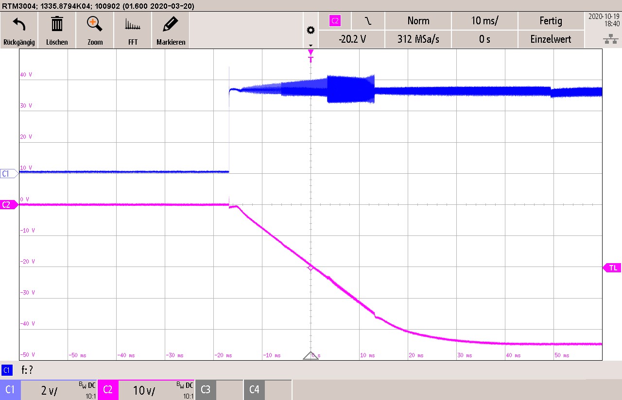
The bandwidth was set to 20 MHz for both channels and soft start was set around 40 ms to 50 ms.

GUID-20220401-SS0I-ZJWX-DZK0-RT7N3SL543RF-low.jpg

Channel C1

input voltage


Channel C2

output voltage

Figure 3-6 Start-up Sequence