TIDT295 August   2022


  1.   Description
  2.   Features
  3.   Applications
  4. 1Test Prerequisites
    1. 1.1 Voltage and Current Requirements
    2. 1.2 Required Equipment
    3. 1.3 Considerations
    4. 1.4 Dimensions
    5. 1.5 Test Setup
  5. 2Testing and Results
    1. 2.1 Efficiency Graphs
    2. 2.2 VOUT Regulation
    3. 2.3 Thermal Images
  6. 3Waveforms
    1. 3.1 Start-up Waveforms
    2. 3.2 Output Voltage Ripple and Noise
    3. 3.3 Load Dynamic
    4. 3.4 Switching Node
    5. 3.5 Short-Circuit Protection

Test Setup

  • The TPS65987 EVM works as PD compliance source or sink to simulate the battery charge and OTG function
  • Place a 47-μF bus capacitor physically close to the output terminal to avoid a long cable connection to the battery side when performing the test
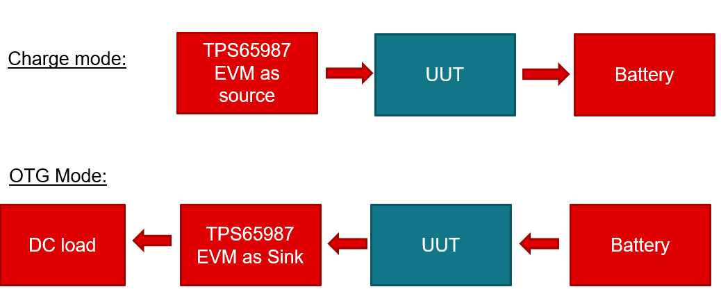
GUID-20220812-SS0I-RSPZ-KBVV-FQMMS6X2CNTN-low.png Figure 1-1 System Test Setup