TIDUEY0 November 2020
- Description
- Resources
- Features
- Applications
- 5
- 1System Description
- 2System Overview
- 3Hardware, Software, Testing Requirements, and Test Results
- 4Design and Documentation Support
- 5About the Author
3.4.1 Constant Control Accuracy ADS131M08 Feedback
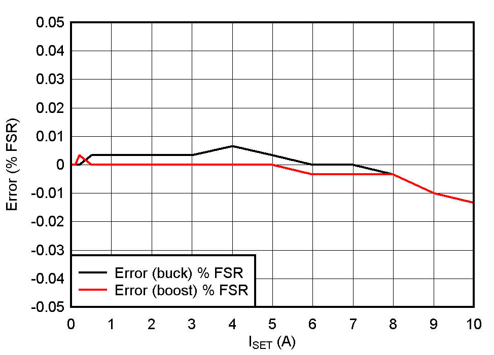
The current accuracy depends on the current-sensing resistor, the gain, offset, and drift of the current amplifier, INA821, and TLV07 devices. These parameters vary from device to device. To achieve good current-control accuracy, the total gain and the offset of the designed circuit must be calibrated. Figure 3-11 shows current error after calibration at room temperature with ADS131M08 in the feedback. It can be seen that error increases at high output current > 8 A. This is due to heating of the current-sense resistor at higher output current. This error can be reduced by using smaller current-sense resistors such as 2 to 3 mΩ for 10-A output current.
 Figure 3-11 Constant-Current Control
Accuracy ADS131M08 Feedback.
 Current feedback noise may change the average output current with variation in battery voltage. Table 3-1 shows output current under different battery voltage and current settings. The test data shows that variation in battery voltage has very little effect on the current.
| Vbat | Iset | |||||||||
|---|---|---|---|---|---|---|---|---|---|---|
| 0.01 A | 0.1 A | 1 A | 6 A | 10 A | 0.01 A | 0.1 A | 1 A | 6 A | 10 A | |
| Charge Mode | Discharge Mode | |||||||||
| 0.5 | 0.0103 | 0.1003 | 1.0007 | 6.001 | 10.001 | 0.01 | 0.1 | 1.0003 | 6.0003 | - |
| 1 | 0.0103 | 0.1003 | 1.0007 | 6.001 | 10.0007 | 0.01 | 0.1003 | 1.0003 | 6.0003 | 9.9993 |
| 2 | 0.0103 | 0.1003 | 1.0007 | 6.0007 | 10.0003 | 0.01 | 0.1003 | 1 | 6 | 9.9993 |
| 3 | 0.0103 | 0.1003 | 1.0007 | 6.0007 | 10 | 0.01 | 0.1 | 1 | 6 | 9.999 |
| 4 | 0.0103 | 0.1 | 1.0007 | 6.0007 | 9.9997 | 0.01 | 0.1 | 1 | 6 | 9.999 |
| 5 | 0.0103 | 0.1 | 1.0007 | 6.001 | 9.9997 | 0.01 | 0.1 | 1 | 6 | 9.999 |
| Variation (% FSR) | 0 | 0.003% | 0 | 0.003% | 0.013% | 0 | 0 | 0.003% | 0.003% | 0.003% |