TIDUF55 November 2023
3.4.3 Relay Driving
The coil driving circuit uses one channel of the smart high-side switch TPS4H160-Q1 and ULN2803 to implement a unidirectional drive, as Figure 3-17 shows. For testing this circuit, a high-voltage relay with economizer is used as the load, EVC500 is described in Table 3-19.
| OPERATING VOLTAGE RANGE / VDC | INRUSH CURRENT AT 23°C/A |
MAXIMUM INRUSH TIME/ms | NOMINAL FREQUENCY/kHz | NOMINAL DUTY CYCLE/% |
|---|---|---|---|---|
| 9 – 36 | 3.8 | 130 | 19.9 | 20 |
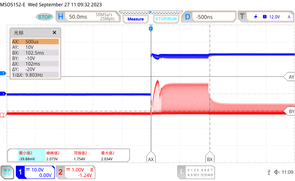
Figure 3-17 shows an oscilloscope plot of the signals during current pickup. Channel 1 shows the voltage on the relay coil; Channel 2 shows the shunt (1.35 Ω) voltage which corresponds to the shunt current through the high-side switch to the relay coil and economizer. Initially the current reaches a peak when the economizer operates in 100% duty cycle, and thus has only a small back electromotive force voltage. After the relay contacts close, the economizer operates in a nominal duty cycle. In the current pick-up process, the shunt voltage signal reaches peak of about 2.034 V. The scale factor for the shunt voltage signal is about 1.35 V/A of shunt current, so this signal indicates the peak current is about 1.507 A.
 Figure 3-9 Current Pickup Phase
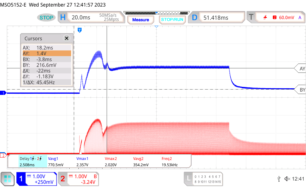
Figure 3-17 shows an oscilloscope plot of the current signals. Channel 1 shows the current sensing (CS) signal of TPS4H160B which corresponds to the current through the high-side switch to the relay coil and economizer. Channel 2 shows the shunt voltage. The shunt voltage signal is followed closely by the CS signal. The CS signal setting time from IN falling and the rising edge of TPS4H160 is a maximum 150 μs, which causes the CS signal to lose the PWM portion of the real shunt current.
 Figure 3-10 Current Measuring
Performance
Figure 3-10 Current Measuring
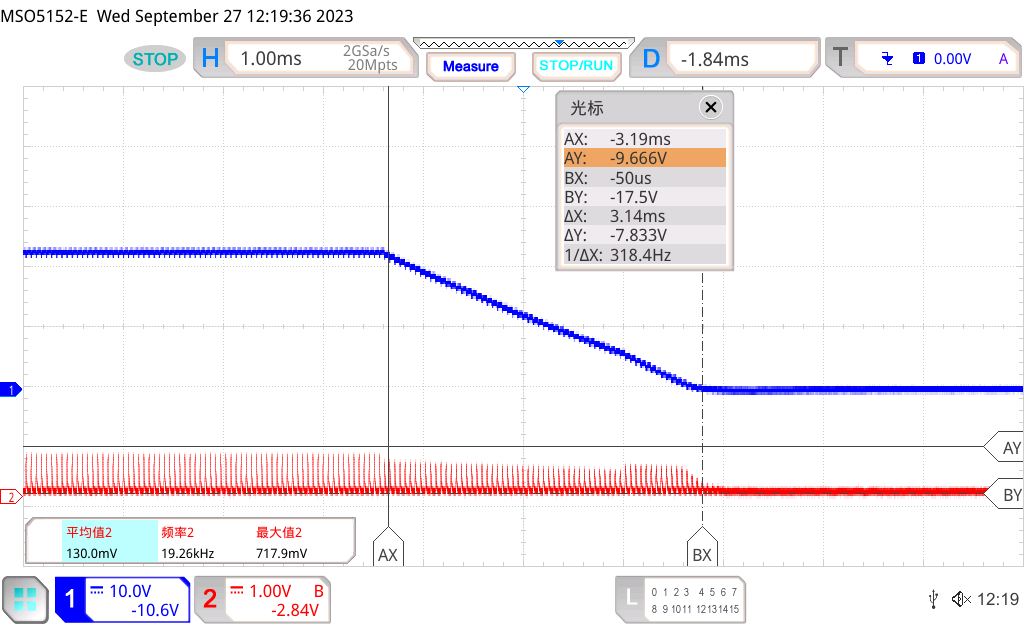
PerformanceFigure 3-17 shows an oscilloscope plot of the signals during the current fast decay phase of the relay. Channel 1 shows the voltage on the relay coil; Channel 2 shows the shunt voltage. The voltage on Channel 1 reduces and the coil current begins to reduce. Due to the inductance of the coil, the coil current does not immediately drop to zero, but decays as the energy stored in the coil dissipates. The fast decay process lasts 3.14 ms.
 Figure 3-11 Current Fast Decay
Phase
Figure 3-11 Current Fast Decay
PhaseThe TPS4H160-Q1 specifies an absolute maximum of 40 mJ for the Inductive load switch-off energy dissipation, single pulse, single channel, so this energy that must be dissipated each time the relay coil is turned off is significantly less than the specified value. Designers can use the TPS4H160-Q1 for this application without the need for protection diodes in parallel with relay coil, unless the coil is significantly larger than the model used for testing.