TIDUFB9 April   2025


  1.   1
  2.   Description
  3.   Resources
  4.   Features
  5.   Applications
  6.   6
  7. 1System Description
  8. 2System Overview
    1. 2.1 Block Diagram
    2. 2.2 Design Considerations
      1. 2.2.1 Reference Design Features
      2. 2.2.2 Switch Settings
    3. 2.3 Highlighted Products
      1. 2.3.1 IWRL6432W
      2. 2.3.2 Crystal
      3. 2.3.3 TPS6285020M – 1.8V DC/DC Regulator
      4. 2.3.4 QSPI Flash Memory
  9. 3System Design Theory
    1. 3.1 Antenna
      1. 3.1.1 Range and Phase Compensation
      2. 3.1.2 Chirp Configuration
    2. 3.2 PCB
  10. 4Hardware, Software, Testing Requirements, and Test Results
    1. 4.1 Hardware Requirements
      1. 4.1.1 Reference Design
      2. 4.1.2 Small Form-Factor Reference Design
    2. 4.2 Software Requirements
    3. 4.3 Test Setup
    4. 4.4 Test Results
      1. 4.4.1 Human Detection at 15 Meters in Boresight
      2. 4.4.2 Antenna Radiation Plots
      3. 4.4.3 Angle Estimation Accuracy
  11. 5Design and Documentation Support
    1. 5.1 Design Files
      1. 5.1.1 Schematics
      2. 5.1.2 BOM
    2. 5.2 Tools and Software
    3. 5.3 Documentation Support
    4. 5.4 Support Resources
    5. 5.5 Trademarks
  12. 6About the Authors

Antenna Radiation Plots

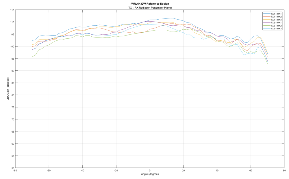
Antenna radiation pattern and angle error across FoV were processed in MATLAB with the raw data collected from the anechoic chamber.


TIDEP-01040 Measured Radiation Pattern
                    (Azimuth)

Figure 4-6 Measured Radiation Pattern (Azimuth)
TIDEP-01040 Measured Radiation Pattern
                    (Elevation)

Figure 4-7 Measured Radiation Pattern (Elevation)