SBOA193B December 2020 – March 2022 INA168 , INA169 , INA240 , INA280 , INA290 , INA293
A Programmable Logic Controller (PLC) is the most widely accepted computer protocol in industrial control systems for factory automation application. PLC system is a controller that controls, prioritizes, and provides status of the system. The controller is programmed via basic binary logic much like a modern computer. The PLC system consists of:
- PLC computer processor
- The power supply rack
- Back plane for power
- Digital input and output module
- Analog input and output module
- Computer software
- A network interface for remote connectivity
PLC systems are widely used in industrial applications that is accelerating industrial 4.0 revolution. PLC systems are enabling faster integration of semiconductor devices for control and automation to increase efficiency and improve factory throughput. Industrial automation and integration examples include controlling of temperature, turning on and off a light fault indication, weighing of a package using pressure sensors, turning on and off a solenoid relay.
As industrial systems can be noisy environments with high-frequency signals and noise coupling into low-voltage signals, the PLC system's output modules are optocoupled. Its robustness to noise, simple architecture, ease of programming language, industrial certifications, and safety features are the reasons PLC systems are the most widely used industrial protocol.
PLC System Block Diagram
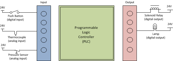
The inputs and outputs of the PLC system are categorized as digital or analog as illustrated in Figure 1-1. The digital inputs provide an ON-OFF status to the control circuitry. Some examples of digital input devices include limit switches, photoelectric sensor, proximity, and pressure sensor. Analog input devices such as thermocouples, tachometers, and force sensors provide variable output responses.
PLC digital outputs are used to turn ON-OFF the starter to engage a motor, to turn on a lamp to indicate a fault, or to control the solenoid that engages relay. The analog outputs include current level output and resistance level that can be used to control and monitor heaters or control the speed of a motor.
 Figure 1-1 PLC System Block Diagram
Discrete PLC Digital Outputs Safety
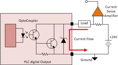
Figure 1-2 illustrates a description of a PLC digital output circuit. PLC digital outputs are designed with high-drive strength capability that can be as high as 1 A. The digital outputs can be connected to drive a solenoid relay to take control of an action initiated by the PLC controller. Discrete current sensors connected in series with the load, as shown in Figure 1-2, monitor current flowing to the load continuously and report the presence of excessive currents to the controller to take an action. As PLC digital outputs can swing from –0.7 V to 24 V, a high-side current sense amplifier with low-offset and low-gain error enables safety for high-output drives.
 Figure 1-2 PLC Digital Output Sinking
 Current Circuit
As the PLC digital output drive can be high, the sinking current capability is one of the key safety parameters. The outputs are designed with NPN transistors with a built in diodes for over voltage protection. The system ensures that when the PLC digital outputs are engaged the sinking current from the power supply is always within the PLC's specified, over temperature operating range. A discrete current sense amplifier can protect the digital outputs from an overcurrent condition, provide diagnostics to address faulty load conditions and address preventive action for premature system failure.
High-Current PLC Digital Outputs Safety
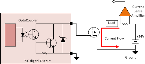
PLC digital outputs can be directly tied to high-current solenoid drivers or high-current LED lamps to close relays or to indicate a fault in a factory automation application. If the current output drive is higher than the PLC system is rated for, a discrete FET can be used to control the current flow form the 24-V supply to the load. Figure 1-3 illustrates the connection of a PLC digital output to an external low RDS on FET to further increase the output drive strength. One disadvantage of this approach is the reliability of the external FET. Using a current-sensing amplifier to monitor the load current can ensure that the PLC system is operating safely.
 Figure 1-3 PLC Discrete Digital Output
Control
Figure 1-3 PLC Discrete Digital Output
ControlINA240 is a high-precision, bidirectional current sense amplifier with low-input offset and gain drift across temperature range designed for measuring currents on discrete PLC digital outputs. The INA240 is specifically designed to work in switched node environments where the common-mode transients will have large dv/dt signals. The ability to reject high dv/dt signals enables accurate current measurements to ensure necessary protection and meet the required safety standards. The INA240 has low maximum input offset voltage of 25 µV and a maximum gain error of 0.2% allowing for smaller shunt resistance values to be used without sacrificing measurement accuracy. The offset drift and gain error drift is as low as 0.25µV/°C and 2.5ppm/°C respectively enabling accurate and stable current measurements across temperature.
The signal throughput bandwidth of INA240 is 400 kHz at the gain 20. The high bandwidth and high slew rate (2V/µs) enables the amplifier to be used for detecting fast over current or shorted load conditions provided the sampling ADC within the PLC system is fast enough to sample currents.
Alternate Device Recommendations
The INA293 is another device to recommend for this application. The INA293 is a unidirectional current sense amplifier that can support a common-mode voltage from –4 V to 110 V and can survive –20 V to 116 V. This large negative common-mode survivability is important due to inductive kickbacks seen when engaging the solenoid or a motor starter. The INA293 also has a high-bandwidth of 1MHz which enables fast reaction times in the event of an overcurrent scenario.
The INA290 is also another device that can be used in PLC systems. INA290 is designed to operate with a common-mode voltage range from 2.7 V to 110 V. Although this is a high-side sense device, the INA290 can survive common-mode transients of –20 V to 120 V.
| Device | Optimized Parameter | Performance Trade-Off |
|---|---|---|
| INA293 | Bandwidth : 1.3 MHz, VCM: –4 V to 110 V, Offset voltage: 15 µV, Gain error: 0.15% |
N/A |
| INA281 | Bandwidth : 1.3 MHz, VCM: –4 V to 110 V, Cost Optimized |
Offset voltage: 55 µV, gain error: 0.5 |
| INA290 | Bandwidth: 1.1 MHz, Offset voltage: 12 µV, Gain error: 0.1%, Package: SC-70 |
High-side only (VCM: -4 to 110V) |
| INA280 | Bandwidth: 1.1 MHz, Package: SC-70, Cost Optimized |
Offset Voltage: 150 μV, Gain error: 0.5% |