SBOA496 January 2021 BUF634 , BUF634A , OPA2810 , OPA656 , OPA810 , THS4551
1 Application Brief
Introduction
LCR meters and impedance analyzers are used to measure unknown values of passive components like resistors, capacitors, inductors, or a combination of these elements. These lab equipment are similar, except that an impedance analyzer allows measurements at different test frequencies. The auto-balancing (ABB) method, compared to the other architectures, offers good measurement accuracy over a wide range of values of impedance, and is discussed in this technical report.
Auto-Balancing Method
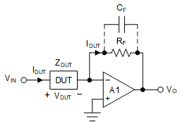
Figure 1-1 shows a representative schematic of an analog front-end using the ABB method. ZDUT is the unknown impedance (device under test or DUT) and RF is a known feedback resistance in this circuit. A known voltage VIN is forced at input to the signal chain. For a voltage VDUT across ZDUT and a current IDUT flowing through it,

Amplifier A1 is used as an inverting amplifier, whose output voltage is given as,


From (1) and (3), the unknown impedance ZDUT is given by,


Figure 1-1 Representative Schematic of an LCR Meter Analog Front-End Using ABB Method
Design Challenges
A few things need careful consideration when designing an LCR meter analog front-end circuit using the ABB method:
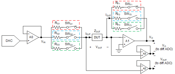
- A single value of RF will not suffice for measuring a wide range of values of ZDUT. To increase the measurement range and sensitivity of the LCR meter multiple feedback resistors (RF1,2,3) are switched into the circuit through series switches (SWF1,2,3), shown in Figure 1-2.
- A large value of RF forms a zero in the noise-gain transfer function causing 40 dB/decade rate-of-closure and potential instability. Use of a capacitor CF in parallel with the large RF, shown in Figure 1-1, introduces a pole to cancel this zero and restores phase margin, but it is difficult to find a single value of CF for stability with all values of capacitive ZDUT. This problem is solved using series resistors RG1,2,3 with ZDUT, as Figure 1-2 shows. Use of RG introduces a pole in noise-gain, cancelling the zero and restoring phase for a stable circuit. Multiple values of RG (equal to corresponding RF1,2,3) with corresponding series switches (SWG1,2,3) need to be used. The same RF and RG pairs (marked with the same color in Figure 1-2) are switched in every time for the required measurement range to ensure stable operation.
- For high accuracy measurements with large value DUTs, VDUT and IDUT should be buffered with high-Z input amplifiers (A2 and A3 here, CMOS or FET-input amplifiers with ≈pA range bias currents).
 Figure 1-2 Modified Circuit for High-Frequency
Measurements Needing More Amplifiers and Differential ADCs
Figure 1-2 Modified Circuit for High-Frequency
Measurements Needing More Amplifiers and Differential ADCsAmplifier A3 can be eliminated for a simplified analog front-end design; however, to maintain measurement accuracy, amplifier A1 should have a large enough open-loop gain (AOL), and hence a gain-bandwidth product at the highest measurement frequency of interest. With a large AOL at the test frequency, a virtual ground is maintained at A1’s inverting input.
Eliminating A3 allows for single-point ground-referenced measurements with need for smaller number of amplifier channels and single-ended ADCs. A general rule-of-thumb is to ensure that A1 has >60-dB AOL at the highest frequency of interest for high accuracy measurements. For higher test frequencies, two-point measurements for VDUT and IDUT are needed to calculate ZDUT with high-accuracy, which requires more amplifiers (A3 in Figure 1-2) and differential input ADCs.
Conclusion
The TIDA-060029 reference design describes this LCR meter analog front-end and the associated challenges in detail. An analog front-end with impedance measurements accurate to 0.1% is implemented in this reference design. Impedance values in the range 1 Ω to 10 MΩ can be measured at frequencies from 100 Hz to 100 kHz. Table 1-1 lists Texas Instruments amplifiers suitable for use in an LCR meter design:
| Device | Architecture | GBW | Quiescent Current | Noise | Function |
|---|---|---|---|---|---|
| OPA810 | FET-input, voltage-feedback | 70 MHz | 3.7 mA | 6.3 nV/rtHz | Unity-gain buffer for VDUT and IDUT measurements |
| OPA656 | FET-input, voltage-feedback | 230 MHz | 14 mA | 7 nV/rtHz | High-frequency VDUT and IDUT measurements |
| THS4551 | Low-power fully differential amplifier | 135 MHz | 1.37 mA | 3.3 nV/rtHz | ADC input driver for differential VDUT and IDUT measurements |
| BUF634A | High IOUT buffer | 210 MHz | 8.5 mA | 3.4 nV/rtHz | High IOUT buffer for driving small-value DUT with VIN |