SWRU553A September 2019 – February 2020
-
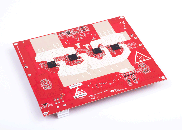
AWRx Cascaded Radar RF Evaluation Module (MMWCAS-RF-EVM)
- Trademarks
- 1 Getting Started
- 2 Hardware Description
- 3 Design Files and Software Tools
- 4 PCB Dimensions and Mounting Information
- 5 PCB Storage and Handling Recommendations
- 6 References
- 7 Regulatory Information
- Revision History
AWRx Cascaded Radar RF Evaluation Module
(MMWCAS-RF-EVM)