SNVS500C July 2007 – November 2016 LP5524
PRODUCTION DATA.
- 1 Features
- 2 Applications
- 3 Description
- 4 Revision History
- 5 Pin Configuration and Functions
- 6 Specifications
- 7 Detailed Description
- 8 Application and Implementation
- 9 Power Supply Recommendations
- 10Layout
- 11Device and Documentation Support
- 12Mechanical, Packaging, and Orderable Information
Package Options
Mechanical Data (Package|Pins)
- YFQ|9
Thermal pad, mechanical data (Package|Pins)
Orderable Information
1 Features
- Wide Input Voltage Range: 2.7 V to 5.5 V
- High-Side LED Driver
- Drives Four LEDs With up to 25 mA per LED
- 0.4% Typical Current Matching
- PWM Brightness Control
- Overcurrent Protection
- Fast Transient Response
- Optional External ISET Resistor
- Ultra-Small Solution Size:
- No External Components
- 9-Pin DSBGA Package with 0.4-mm pitch:
- 1.24 mm × 1.24 mm × 0.6 mm (L × W × H, maximum)
2 Applications
- Sub-Display Backlight
- Keypad LED Backlight
- Indicator LED
3 Description
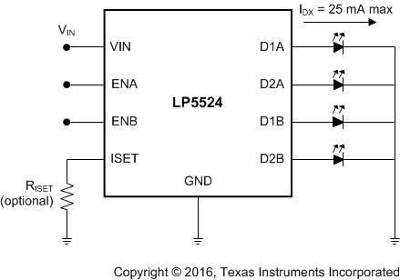
The LP5524 device is a highly integrated dual-zone LED driver that can drive up to four LEDs in parallel with a total output current of 100 mA. Regulated high-side internal current sources deliver excellent current and brightness matching in all LEDs.
The LP5524 provides overcurrent protection and pulse-width modulation (PWM) control of four indicator LEDs without the need for external components.
LED driver current sources are split into two independently controlled banks for driving secondary displays, keypad and indicator LEDs. Brightness control is achieved by applying PWM signals to each enable pin. Default LED current is factory-programmable and an optional external resistor can be used to set LED current to user programmable values.
The LP5524 is available in a tiny, 9-pin, thin DSBGA package.
Device Information(1)
| PART NUMBER | PACKAGE | BODY SIZE (NOM) |
|---|---|---|
| LP5524 | DSBGA (9) | 1.21 mm × 1.21 mm |
space
space
space
space
Simplified Schematic
