SLLS983L June 2009 – October 2023 ISO1050
PRODUCTION DATA
- 1
- 1 Features
- 2 Applications
- 3 Description
- 4 Revision History
- 5 Pin Configuration and Functions
-
6 Specifications
- 6.1 Absolute Maximum Ratings
- 6.2 ESD Ratings
- 6.3 Recommended Operating Conditions
- 6.4 Thermal Information
- 6.5 Power Ratings
- 6.6 Insulation Specifications
- 6.7 Safety-Related Certifications
- 6.8 Safety Limiting Values
- 6.9 Electrical Characteristics - DC Specification
- 6.10 Switching Characteristics
- 6.11 Insulation Characteristics Curves
- 6.12 Typical Characteristics
- 7 Parameter Measurement Information
- 8 Detailed Description
- 9 Application and Implementation
- 10Power Supply Recommendations
- 11Layout
- 12Device and Documentation Support
- 13Mechanical, Packaging, and Orderable Information
Package Options
Mechanical Data (Package|Pins)
Thermal pad, mechanical data (Package|Pins)
Orderable Information
3 Description
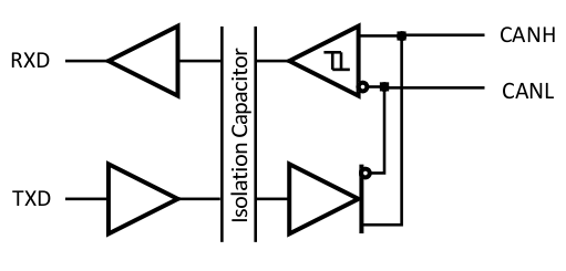
The ISO1050 is a galvanically isolated CAN transceiver that meets the specifications of the ISO11898-2 standard. The device has the logic input and output buffers separated by a silicon oxide (SiO2) insulation barrier that provides galvanic isolation of up to 5000 VRMS for ISO1050DW and 2500 VRMS for ISO1050DUB. Used in conjunction with isolated power supplies, the device prevents noise currents on a data bus or other circuits from entering the local ground and interfering with or damaging sensitive circuitry.
As a CAN transceiver, the device provides differential transmit capability to the bus and differential receive capability to a CAN controller at signaling rates up to 1 megabit per second (Mbps). The device is designed for operation in especially harsh environments, and it features cross-wire, overvoltage and loss of ground protection from –27 V to 40 V and overtemperature shutdown, as well as –12V to 12V common-mode range.
The ISO1050 is characterized for operation over the ambient temperature range of –55°C to 105°C.
| PART NUMBER | PACKAGE | PACKAGE SIZE ((2)) |
|---|---|---|
| ISO1050 | SOP (8) | 9.5 mm × 10.4 mm |
| SOIC (16) | 10.3 mm × 10.3 mm |
 Simplified Schematic