SNOSCZ7B December   2015  – April 2024 LDC0851

PRODUCTION DATA  

  1.   1
  2. Features
  3. Applications
  4. Description
  5. Pin Configuration and Functions
  6. Specifications
    1. 5.1 Absolute Maximum Ratings
    2. 5.2 ESD Ratings
    3. 5.3 Recommended Operating Conditions
    4. 5.4 Thermal Information
    5. 5.5 Electrical Characteristics
    6. 5.6 Interface Voltage Levels
    7. 5.7 Timing Requirements
    8. 5.8 Typical Characteristics
  7. Detailed Description
    1. 6.1 Overview
    2. 6.2 Functional Block Diagram
    3. 6.3 Feature Description
      1. 6.3.1 Basic Operation Mode
      2. 6.3.2 Threshold Adjust Mode
      3. 6.3.3 Setting the Threshold Adjust Values
      4. 6.3.4 Hysteresis
      5. 6.3.5 Conversion Time
      6. 6.3.6 Power-Up Conditions
    4. 6.4 Device Functional Modes
      1. 6.4.1 Shutdown Mode
      2. 6.4.2 Active Mode
  8. Application and Implementation
    1. 7.1 Application Information
      1. 7.1.1 Sensor Design
        1. 7.1.1.1 Sensor Frequency
        2. 7.1.1.2 Sensor Design Procedure
    2. 7.2 Typical Application
      1. 7.2.1 Event Counting
        1. 7.2.1.1 Design Requirements
        2. 7.2.1.2 Detailed Design Procedure
        3. 7.2.1.3 Application Curves
      2. 7.2.2 Coarse Position Sensing
        1. 7.2.2.1 Design Requirements
        2. 7.2.2.2 Detailed Design Procedure
        3. 7.2.2.3 Application Curves
      3. 7.2.3 Low Power Operation
        1. 7.2.3.1 Design Requirements
        2. 7.2.3.2 Detailed Design Procedure
        3. 7.2.3.3 Application Curves
    3. 7.3 Power Supply Recommendations
    4. 7.4 Layout
      1. 7.4.1 Layout Guidelines
      2. 7.4.2 Layout Example
        1. 7.4.2.1 Side by Side Coils
        2. 7.4.2.2 Stacked Coils
  9. Device and Documentation Support
    1. 8.1 Device Support
      1. 8.1.1 Development Support
    2. 8.2 Documentation Support
      1. 8.2.1 Related Documentation
    3. 8.3 Support Resources
    4. 8.4 Trademarks
    5. 8.5 Electrostatic Discharge Caution
    6. 8.6 Glossary
  10. Revision History
  11. 10Mechanical, Packaging, and Orderable Information

Package Options

Mechanical Data (Package|Pins)
Thermal pad, mechanical data (Package|Pins)
Orderable Information

Active Mode

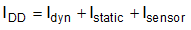
When the LDC0851 EN pin is pulled high, the LDC0851 is put into active mode. The active supply current (IDD) is broken up into three pieces: Static current (Istatic), Dynamic current (Idyn), and Sensor current (Isensor).

Static current is the DC device current given in the electrical characteristics and does not vary over frequency.

Dynamic current is the AC device current which varies with both sensor frequency (ƒSENSOR) and board parasitic capacitance (CBOARD). Dynamic current can be computed with the following equation:

Equation 3. GUID-3CBDABC0-5190-460B-9AF4-7BFC4A13186A-low.gif

where:

  • Idyn is the dynamic current drawn by the device and board parasitics
  • ƒSENSOR is the sensor frequency calculated from Equation 6
  • CBOARD is the parasitic capacitance of the board, see Figure 7-1

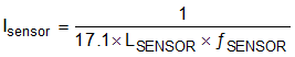
Sensor current is the AC current required to drive an external LC sensor. Sensor current varies with both the frequency and inductance of the sensor and is given by the following equation:

Equation 4. GUID-37168641-90B7-4F65-BFCC-281A50943B45-low.gif

where:

  • ISENSOR is current required to drive the sensor
  • LSENSOR is the measured inductance of the sensor
  • ƒSENSOR is the sensor frequency calculated from Equation 6

The total active supply current is given by the following equation:

Equation 5. GUID-9300E9BE-D90B-425C-88E4-02D6A0F6DA23-low.gif

where:

  • IDD is the total active supply current
  • Idyn is the dynamic current drawn by the device as given by Equation 3
  • Istatic is the static current as given in the electrical table
  • ISENSOR is current required to drive the sensor as given by Equation 4