SNOSCZ7B December 2015 – April 2024 LDC0851
PRODUCTION DATA
- 1
- 1 Features
- 2 Applications
- 3 Description
- 4 Pin Configuration and Functions
- 5 Specifications
- 6 Detailed Description
- 7 Application and Implementation
- 8 Device and Documentation Support
- 9 Revision History
- 10Mechanical, Packaging, and Orderable Information
Package Options
Mechanical Data (Package|Pins)
- DSG|8
Thermal pad, mechanical data (Package|Pins)
- DSG|8
Orderable Information
6.3.2 Threshold Adjust Mode
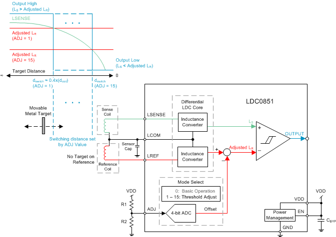
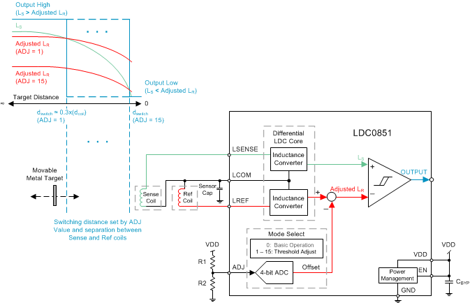
In Threshold Adjust mode, an offset inductance is subtracted from LREF to alter the switching threshold without the use of a reference target. In order to configure the LDC0851 for Threshold Adjust mode, place a resistor divider between VDD and GND as shown in Figure 6-3. The threshold adjust values can then be easily changed as described in section Setting the Threshold Adjust Values. Threshold adjust mode can be used in a variety of applications including coarse proximity sensing and simple button applications as shown in Coarse Position Sensing. Two example coil configurations for proximity sensing are shown below for side by side coil orientation in Figure 6-3 as well as a stacked configuration in Figure 6-4.
 Figure 6-3 Threshold Adjust Mode for Distance Sensing Using Side by Side Coils
Stacked coils can be utilized in designs where PCB space is a concern or if the user only wants to detect proximity to metal from one side of the PCB such as a button application. The sensing range is slightly reduced due to the fact that both the sense and the reference coil are affected by same conductive target, however since the sense coil is closer to the target its respective inductance decreases more than the reference inductance allowing the output to switch as shown in Figure 6-4.
 Figure 6-4 Threshold Adjust Mode for Distance Sensing Using Stacked Coils
To get the most sensing range with stacked coils the spacing between the sensing coil and reference coil (height = h) should be maximized as shown in Figure 6-5. See section Stacked Coils for more information on the layout of stacked coils.
 Figure 6-5 Stacked Coil Separation (PCB Side View)