SNOSAT7G August   2007  – October 2015 LMP7300

PRODUCTION DATA.  

  1. Features
  2. Applications
  3. Description
  4. Revision History
  5. Pin Configuration and Functions
  6. Specifications
    1. 6.1 Absolute Maximum Ratings
    2. 6.2 ESD Ratings
    3. 6.3 Recommended Operating Conditions
    4. 6.4 Thermal Information
    5. 6.5 Electrical Characteristics: 2.7-V
    6. 6.6 Electrical Characteristics: 5-V
    7. 6.7 Electrical Characteristics: 12-V
    8. 6.8 Typical Characteristics
  7. Detailed Description
    1. 7.1 Overview
    2. 7.2 Functional Block Diagram
    3. 7.3 Feature Description
      1. 7.3.1 Voltage Reference
      2. 7.3.2 Comparator
        1. 7.3.2.1 Output Stage
        2. 7.3.2.2 Fault Detection Rate
      3. 7.3.3 Hysteresis
        1. 7.3.3.1 How Much Hysteresis Is Correct?
    4. 7.4 Device Functional Modes
  8. Application and Implementation
    1. 8.1 Application Information
    2. 8.2 Typical Applications
      1. 8.2.1 Window Comparator
        1. 8.2.1.1 Design Requirements
        2. 8.2.1.2 Detailed Design Procedure
        3. 8.2.1.3 Application Curve
      2. 8.2.2 Precision High-Temperature Switch
        1. 8.2.2.1 Design Requirements
      3. 8.2.3 Micropower Precision-Battery Low-Voltage Detector
        1. 8.2.3.1 Design Requirements
  9. Power Supply Recommendations
  10. 10Layout
    1. 10.1 Layout Guidelines
    2. 10.2 Layout Example
  11. 11Device and Documentation Support
    1. 11.1 Device Support
      1. 11.1.1 Development Support
        1. 11.1.1.1 Evaluation Boards
    2. 11.2 Community Resources
    3. 11.3 Trademarks
    4. 11.4 Electrostatic Discharge Caution
    5. 11.5 Glossary
  12. 12Mechanical, Packaging, and Orderable Information

Package Options

Mechanical Data (Package|Pins)
Thermal pad, mechanical data (Package|Pins)
Orderable Information

10 Layout

10.1 Layout Guidelines

A good PCB layout is always important to reduce output to input coupling. Positive feedback noise reduces performance. For the LMP7300, output coupling is minimized by the unique package pinout. The output is kept away from the noninverting and inverting inputs, the reference and the hysteresis pins.

10.2 Layout Example

The following section shows an example schematic and layout for the LMP7300MA 8-pin SOIC package.
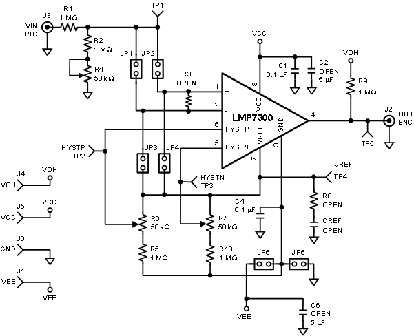
LMP7300 schematic_snosat7.gif Figure 27. LMP7300MA-EVAL Schematic
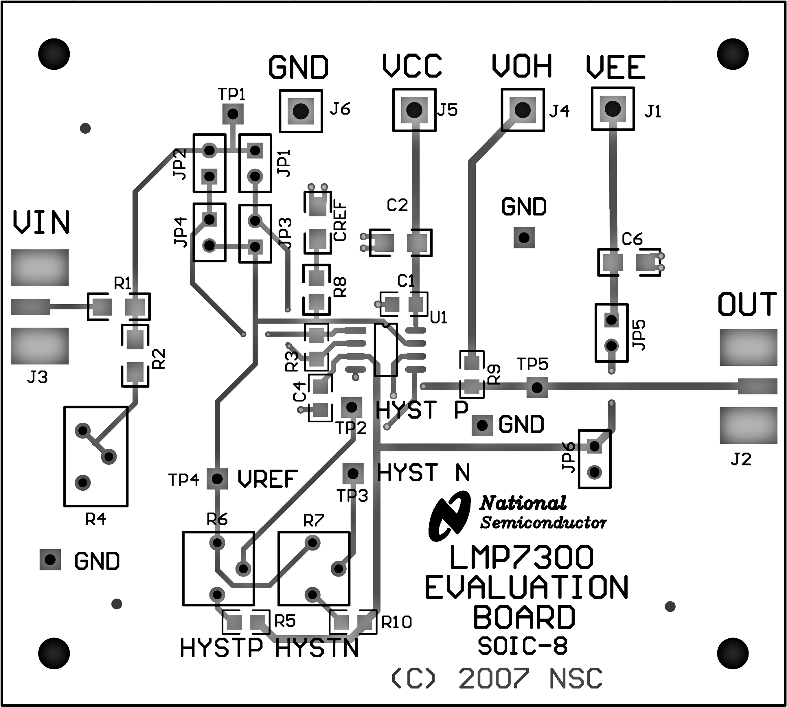
LMP7300 30022308.png Figure 28. LMP7300MA-EVAL Layout Top View
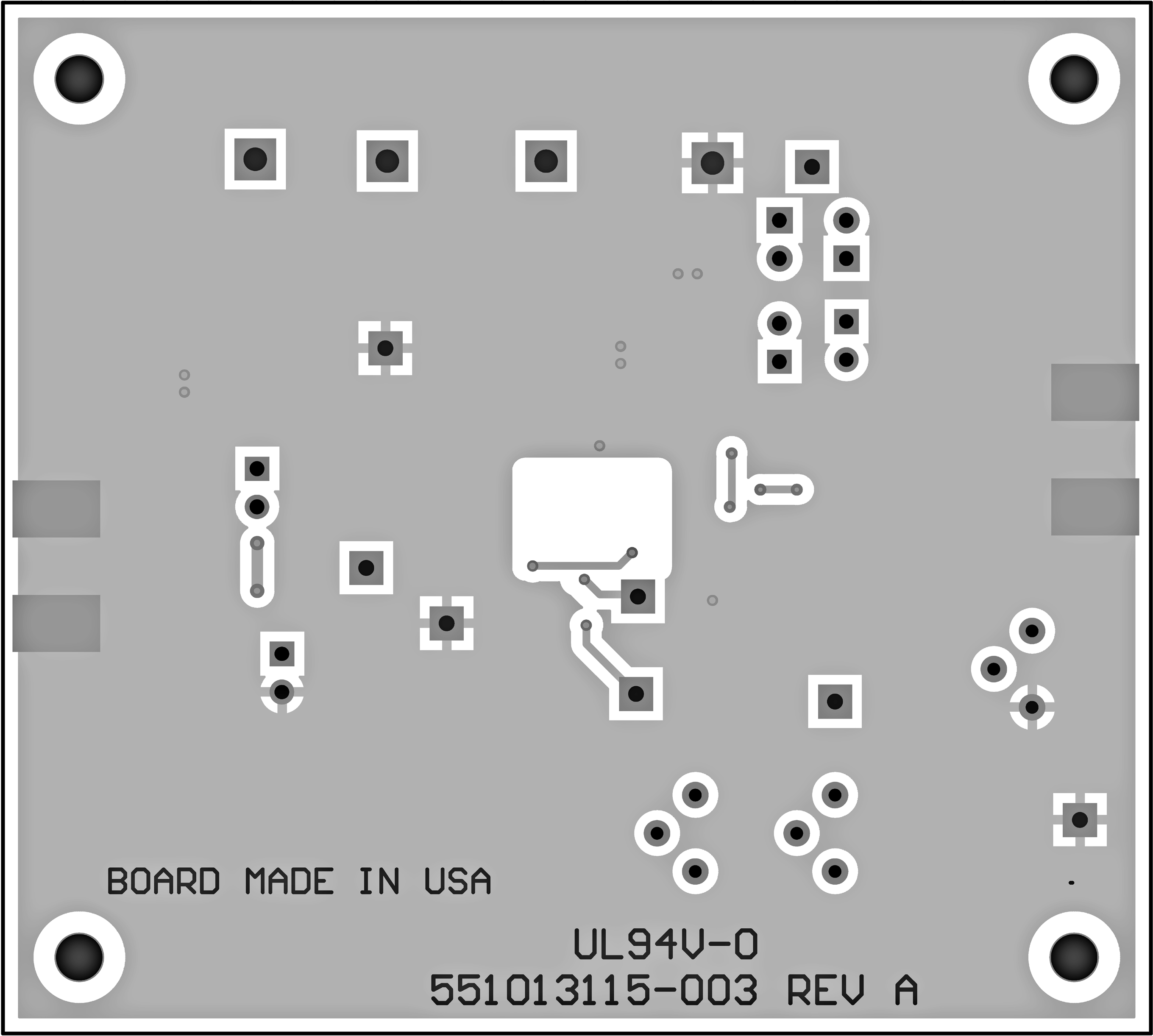
LMP7300 30022305.png Figure 29. LMP7300MA-EVAL Layout Bottom View