SBOS973A June 2019 – September 2019 OPA2834
PRODUCTION DATA.
- 1 Features
- 2 Applications
- 3 Description
- 4 Revision History
- 5 Device Comparison Table
- 6 Pin Configuration and Functions
- 7 Specifications
- 8 Detailed Description
- 9 Application and Implementation
- 10Power Supply Recommendations
- 11Layout
- 12Device and Documentation Support
- 13Mechanical, Packaging, and Orderable Information
Package Options
Mechanical Data (Package|Pins)
- DGK|8
Thermal pad, mechanical data (Package|Pins)
Orderable Information
8.3.4 Driving Capacitive Loads
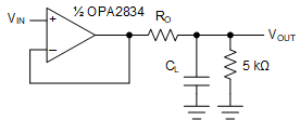
The OPA2834 drives up to a nominal capacitive load of 10 pF on the output with no special consideration and without the need of RO. When driving capacitive loads greater than 10 pF, TI recommends using a small resistor (RO) in series with the output as close to the device as possible. Without RO, output capacitance interacts with the output impedance (ZO) of the amplifier causing phase shift in the feedback loop of the amplifier reducing the phase margin. This reduction in the phase margin causes peaking in the frequency response and overshoot and ringing in the pulse response. Interaction with other parasitic elements can lead to further instability or ringing. Inserting RO isolates the phase shift from the loop gain path and restores the phase margin; however RO can limit the bandwidth slightly. Figure 49 shows a diagram of driving capacitive loads.
Figure 39 shows the test circuit and shows the recommended values of RO versus capacitive loads, CL. See Figure 40 for the frequency responses with various optimized values of RO with CL.
 Figure 49. Driving Capacitive Loads With the OPA2834