JAJSHL4C March   2015  – June 2019 DLPC150

PRODUCTION DATA.  

  1. 特長
  2. アプリケーション
  3. 概要
    1.     Device Images
      1.      DLP 0.2 インチ WVGA チップセット
  4. 改訂履歴
  5. Pin Configuration and Functions
    1.     Pin Functions
    2. 5.1 DLPC150 Mechanical Data
      1. Table 1. I/O Type Subscript Definition
      2. Table 2. Internal Pullup and Pulldown Characteristics
  6. Specifications
    1. 6.1  Absolute Maximum Ratings
    2. 6.2  ESD Ratings
    3. 6.3  Recommended Operating Conditions
    4. 6.4  Thermal Information
    5. 6.5  Electrical Characteristics Over Recommended Operating Conditions
    6. 6.6  Electrical Characteristics
    7. 6.7  High-Speed Sub-LVDS Electrical Characteristics
    8. 6.8  Low-Speed SDR Electrical Characteristics
    9. 6.9  System Oscillators Timing Requirements
    10. 6.10 Power-Up and Reset Timing Requirements
    11. 6.11 Parallel Interface Frame Timing Requirements
    12. 6.12 Parallel Interface General Timing Requirements
    13. 6.13 Flash Interface Timing Requirements
  7. Parameter Measurement Information
    1. 7.1 Host_irq Usage Model
    2. 7.2 Input Source
      1. 7.2.1 Parallel Interface Supports Two Data Transfer Formats
        1. 7.2.1.1 Pdata Bus – Parallel Interface Bit Mapping Modes
  8. Detailed Description
    1. 8.1 Overview
    2. 8.2 Functional Block Diagram
    3. 8.3 Feature Description
      1. 8.3.1 Interface Timing Requirements
        1. 8.3.1.1 Parallel Interface
      2. 8.3.2 Serial Flash Interface
      3. 8.3.3 Serial Flash Programming
      4. 8.3.4 I2C Control Interface
      5. 8.3.5 DMD (Sub-LVDS) Interface
      6. 8.3.6 Calibration And Debug Support
      7. 8.3.7 DMD Interface Considerations
    4. 8.4 Device Functional Modes
  9. Application and Implementation
    1. 9.1 Application Information
      1. 9.1.1 DLPC150 System Design Consideration – Application Notes
    2. 9.2 Typical Application
      1. 9.2.1 Design Requirements
      2. 9.2.2 Detailed Design Procedure
        1. 9.2.2.1 DLPC150 System Interfaces
          1. 9.2.2.1.1 Control Interface
      3. 9.2.3 Application Curve
  10. 10Power Supply Recommendations
    1. 10.1 System Power-Up and Power-Down Sequence
    2. 10.2 DLPC150 Power-Up Initialization Sequence
    3. 10.3 DMD Fast Park Control (PARKZ)
    4. 10.4 Hot Plug Usage
    5. 10.5 Maximum Signal Transition Time
  11. 11Layout
    1. 11.1 Layout Guidelines
      1. 11.1.1 PCB Layout Guidelines For Internal Controller PLL Power
      2. 11.1.2 DLPC150 Reference Clock
        1. 11.1.2.1 Recommended Crystal Oscillator Configuration
      3. 11.1.3 General PCB Recommendations
      4. 11.1.4 General Handling Guidelines for Unused CMOS-Type Pins
      5. 11.1.5 Maximum Pin-to-Pin, PCB Interconnects Etch Lengths
      6. 11.1.6 Number of Layer Changes
      7. 11.1.7 Stubs
      8. 11.1.8 Terminations
      9. 11.1.9 Routing Vias
    2. 11.2 Layout Example
    3. 11.3 Thermal Considerations
  12. 12デバイスおよびドキュメントのサポート
    1. 12.1 デバイス・サポート
      1. 12.1.1 デバイスの項目表記
        1. 12.1.1.1 デバイスのマーキング
    2. 12.2 関連リンク
    3. 12.3 コミュニティ・リソース
    4. 12.4 商標
    5. 12.5 静電気放電に関する注意事項
    6. 12.6 Glossary
  13. 13メカニカル、パッケージ、および注文情報
    1. 13.1 Package Option Addendum
      1. 13.1.1 Packaging Information

パッケージ・オプション

メカニカル・データ(パッケージ|ピン)
サーマルパッド・メカニカル・データ

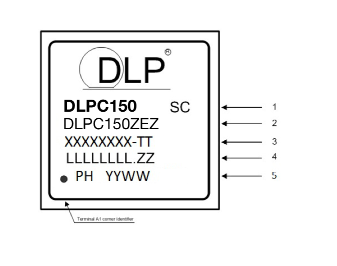
デバイスのマーキング

DLPC150 Dev_Marking.png

マーキングの定義:

1行目: DLP デバイス名:DLPC150
SC: ハンダ・ボール組成
   e1: SnAgCuからなる鉛フリー・ハンダ・ボールを示しています。
   G8: 錫・銀・銅(SnAgCu)からなり、銀の含有量が1.5%以下で、モールド化合物がTIのグリーン規定を満たしている鉛フリー・ハンダ・ボールを示しています。
2 行目: TI 型番
3 行目: XXXXXXXX-TT:製造元の型番
4 行目: LLLLLLLL.ZZ:半導体ウエハーの工場ロット・コードと鉛フリー・半田ボール・マーキング
5行目: PH YYWW:パッケージ組み立て情報