JAJSBP3B November 2011 – December 2018 TMP104
PRODUCTION DATA.
- 1特長
- 2アプリケーション
- 3概要
- 4改訂履歴
- 5Pin Configuration and Functions
- 6Specifications
- 7Detailed Description
- 8デバイスおよびドキュメントのサポート
- 9メカニカル、パッケージ、および注文情報
パッケージ・オプション
デバイスごとのパッケージ図は、PDF版データシートをご参照ください。
メカニカル・データ(パッケージ|ピン)
- YFF|4
サーマルパッド・メカニカル・データ
発注情報
7.4.2.4 Interrupt Functionality (INT_EN)
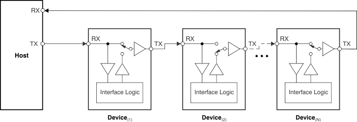
The TMP104 interrupts the host by disconnecting the bus and issuing an interrupt request by holding the bus low if all of these conditions are met, as shown in Figure 15:
- INT_EN in the Configuration Register is set to '1';
- The temperature result is higher than the value in the THIGH register or lower than the value in the TLOW register (as indicated by a '1' in either FL or FH);
- The bus is logic high and idle for more than 28 ms.
 Figure 15. TMP104 Daisy-Chain:
Bus Status During an Interrupt Request (Logic Low) From Second Device
The interrupt on the bus is latched regardless of the status of LC. Writing a '1' to INT_EN automatically sets the LC bit. The TMP104 holds the bus low until one of the following events happen:
- Global Interrupt Clear command received;
- Global Software Reset command received;
- A power-on reset event occurs.
Each of these events clears INT_EN; the TMP104 does not issue future interrupts until the host writes '1' to bit D7 in the Configuration Register to re-enable future interrupts.
In a system with enabled interrupts, it is possible for a TMP104 on the bus to issue an interrupt at the same time that the host starts a communication sequence. To avoid this scenario, it is recommended that the host should check the status on the receiving side of the bus after transmitting the calibration byte. If it is '1', then the host can continue with the communication. If it is '0', one of the TMP104 devices on the bus is issuing an alert and the host must transmit a Global Interrupt Clear command.