SBAU126E may 2007 – june 2023 ADS1158 , ADS1258
7.1 Connecting the Hardware
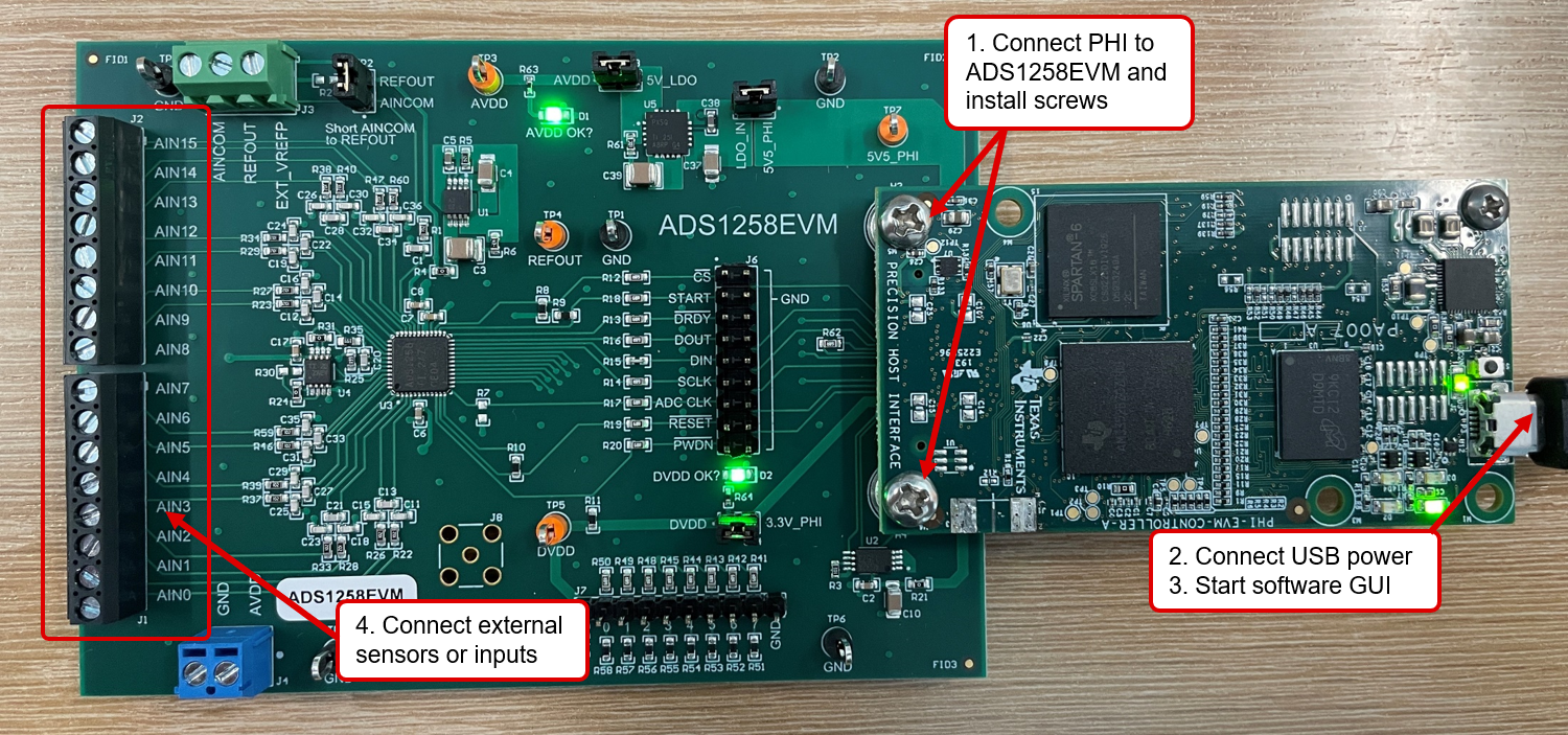
Connect the EVM as shown in Figure 7-1 after installing the software:
- Physically connect P2 of the PHI to J5 of the ADS1258EVM. Install the screws to make a robust connection.
- Connect the USB cable from the computer to the
PHI:
- LED D5 on the PHI lights up, indicating that the PHI is powered up.
- LEDs D1 and D2 on the PHI start blinking to indicate that the PHI is booted up and communicating with the PC. Figure 7-1 shows the resulting LED indicators.
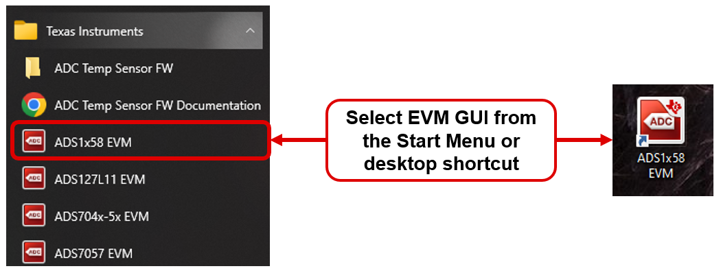
- Start the software GUI as shown in Figure 7-2. The LEDs blink slowly as the FPGA firmware is loaded on the PHI. This loading takes a few seconds and then the AVDD and DVDD power supplies turn on, as indicated by LEDs D1 and D2 on the ADS1258EVM.
- Connect the input signal using terminal blocks J1 and J2. The input range is 0 V to 5 V with the multiplexer loop bypassed. See Section 3.3 for the input range limitations when the multiplexer loop is enabled.
 Figure 7-1 ADS1258EVM Hardware
Connections
 Figure 7-2 Launch the EVM GUI
Software