SBAU362 March 2021 ADS1015 , ADS1115
5.2.3 Configuration
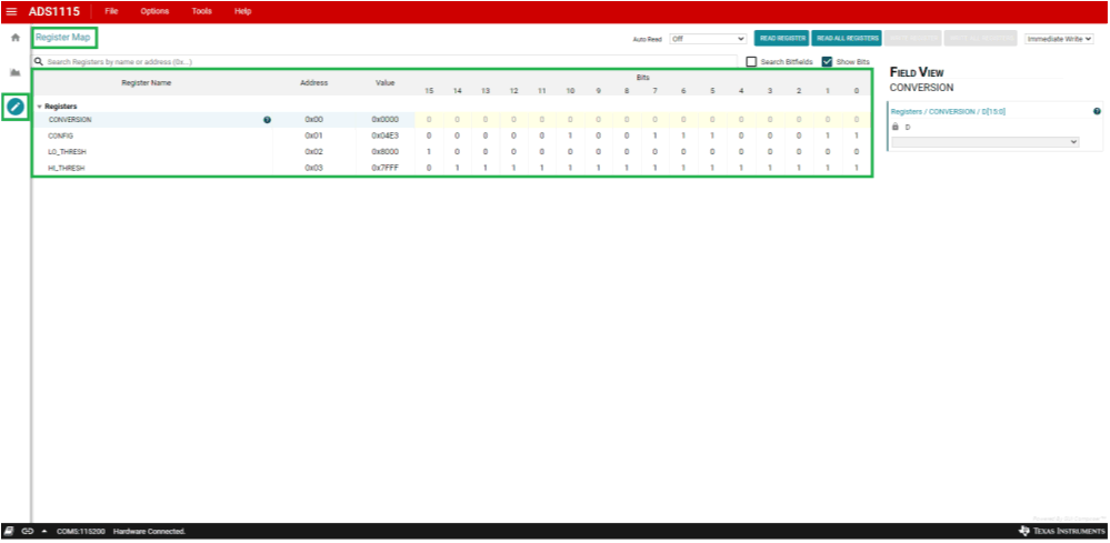
The Register Map window (Figure 5-21) contains information about the configuration and the last conversion data from the ADS1x15. The Conversion register contains the value of the last 16-bit conversion result read from the ADS1115. For the ADS1015, the conversion data are 12-bit left-justified in the 16-bit register.
Because the ADS1x15 is a programmable device, the Config, LoThresh and HiThresh registers are programmable and 16 bits in length.
A number of control buttons and drop-down menus exist to configure the Register Map read and write operations when data are written and read from the ADS1x15.
Question mark icons (?) appear throughout the Register Map window. Clicking these icons opens details pertaining to the items in the locations where they appear.
 Figure 5-21 Register Map
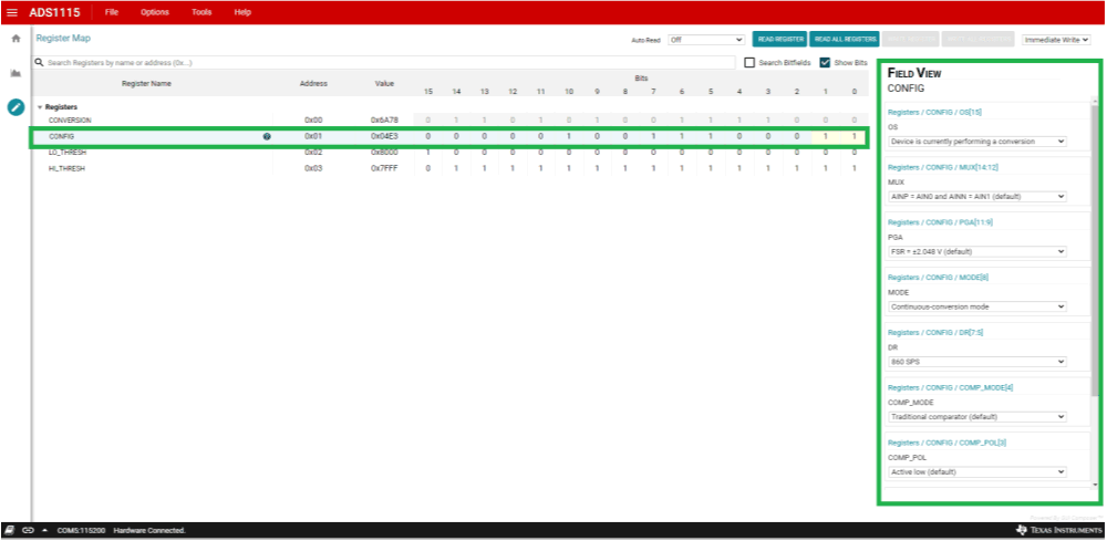
The GUI displays four registers (as shown in Figure 5-22) but only three are configurable in the ADS1x15 device. For the firmware to remain in synchronization with the GUI, all communication is first directed to a pointer register internal to the device and either points to the Conversion register or one of the three configuration registers.
The ADS1x15 primary configuration is accomplished with the Config register. The Register Map data are specific to the GUI and firmware combination for the ADS1x15EVM.
Configuration of the ADS1x15 device is accomplished using the drop-down menu and click options shown in the Field View on the right side of the GUI window. The various bits can also be double-clicked to toggle the bit settings. As the bit settings change, the Field View options also change to correspond to the selection.
 Figure 5-22 ADS1x15 Configuration
The ADS1x15 device also contains an internal comparator. The threshold limits for the comparator are set using the HiThresh and LoThresh registers.