SLAU920 November 2023 DAC80504 , DAC80508
3.2.2.2 High Level Configuration Page
The High Level Configuration page is used to set the configuration of the DAC805xxEVM GUI. The page is comprised of one tab: DAC80504 if the DAC80504 device was selected, or DAC80508 if the DAC80508 device was selected. These two tabs act as shortcuts to configure the DAC80504 and DAC80508 for basic functionality and testing.
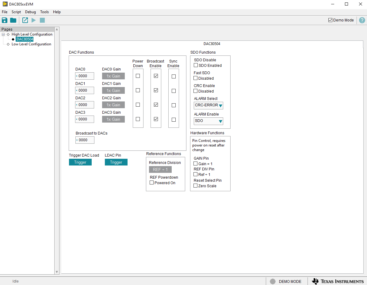
Figure 4-9 shows the DAC80504 tab of the High Level Configuration page. This tab is used to set the gain and output for the DACs. The DAC80504 digital pins can also be controlled here. To use the digital pin GUI functionality, resistors R29, R30, R31, and R32 are required to be populated with 0 Ω resistors. These resistors connect the digital pins to the FTDI GPIO pins. By default, the GAIN, REFDIV, and RSTEL GPIOs are set to 0 V. If the GAIN, REFDIV, or RSTSEL options are changed, the DAC80504 needs to go through a power-on-reset for the changes to take effect. Do not unplug the USB cable to reset the power, as this resets the GPIO pins as well. The internal reference and the reference division can also be powered on and off here.
 Figure 3-9 DAC80504 Tab of the High Level Configuration Page
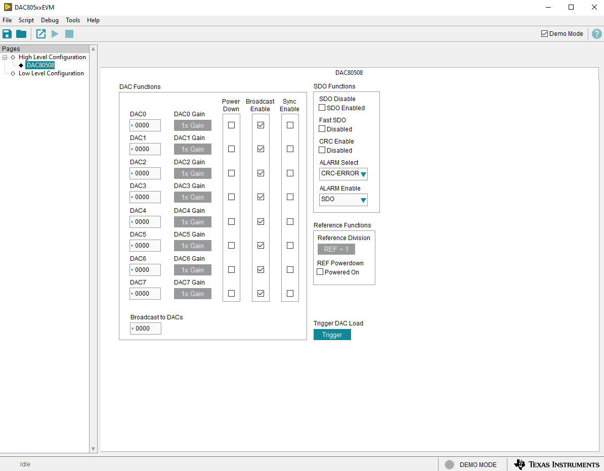
Figure 4-10 shows the DAC80508 tab from the High Level Configuration page. This tab is used to set the gain and output for the DACs. The internal reference and the reference division can also be powered on and off here.
 Figure 3-10 DAC80508 Tab of the High Level Configuration Page