SLUA963B June 2020 – October 2022 UCC21710-Q1 , UCC21732-Q1 , UCC5870-Q1
- HEV/EV Traction Inverter Design Guide Using Isolated IGBT and SiC Gate Drivers
- 1Introduction
- 2HEV/EV Overview
-
3Design of HEV/EV Traction Inverter Drive Stage
- 3.1 Introduction to UCC217xx-Q1
- 3.2 Designing a Traction Inverter Drive System Using UCC217xx-Q1
- 3.3 Description of Protection Features
- 3.4 Protection Features of UCC217xx-Q1
- 3.5
UCC217xx-Q1 Protection and Monitoring Features Descriptions
- 3.5.1 Primary and Secondary Side UVLO and OVLO
- 3.5.2 Over-Current (OC) and Desaturation (DESAT) Detection
- 3.5.3 2-Level and Soft Turn-Off
- 3.5.4 Power Switch Gate Voltage (VGE/VGS) Monitoring
- 3.5.5 Power Switch Anti-Shoot-Through
- 3.5.6 Integrated Internal or External Miller Clamp
- 3.5.7 Isolated Analog-to-PWM Channel
- 3.5.8 Short-Circuit Clamping
- 3.5.9 Active Pulldown
- 3.6 Introduction to UCC5870-Q1
- 3.7 Designing a Traction Inverter Drive System Using UCC5870-Q1
- 3.8 Description of Protection Features
- 3.9 Protection Features of UCC5870-Q1
- 3.10
UCC5870-Q1 Protection and Monitoring Features Descriptions
- 3.10.1 Primary and Secondary Side UVLO and OVLO
- 3.10.2 Programmable Desaturation (DESAT) Detection and Over-Current (OC)
- 3.10.3 Adjustable 2-Level or Soft Turn-Off
- 3.10.4 Active High-Voltage Clamp
- 3.10.5 Power Switch Gate Voltage (VGE/VGS) Monitoring
- 3.10.6 Gate Threshold Voltage Monitor
- 3.10.7 Power Switch Anti-Shoot-Through
- 3.10.8 Active Short Circuit (ASC)
- 3.10.9 Integrated Internal or External Miller Clamp
- 3.10.10 Isolated Analog-to-Digital Converter
- 3.10.11 Short-Circuit Clamping
- 3.10.12 Active and Passive Pulldown
- 3.10.13 Thermal Shutdown and Temperature Warning of Driver IC
- 3.10.14 Clock Monitor and CRC
- 3.10.15 SPI and Register Data Protection
- 4Isolated Bias Supply Architecture
- 5Summary
- 6References
- 7Revision History
2.1 HEV/EV Architectures
The electrification of vehicles has revolutionized the transportation industry and has resulted in technological advancements in both the automotive and semiconductor industries. Electrified vehicles including both hybrid electric (HEV) and full electric (EV) vehicles consist of various power electronics systems for regulating power from the grid, managing the battery storage element, and ultimately driving the vehicle. Electric motors are used to drive the wheels of the vehicle or to act as a generator to transfer mechanical energy into electric energy to store in the battery. HEVs use a combination of electric motors and generators, used as a low-power starter and alternator or to fully drive the vehicle, along with the internal combustion engine (ICE) typically used as the primary source of the vehicle's motion. The EV, on the other hand, utilizes electric motors as the primary source of vehicle motion as well as for regeneration.
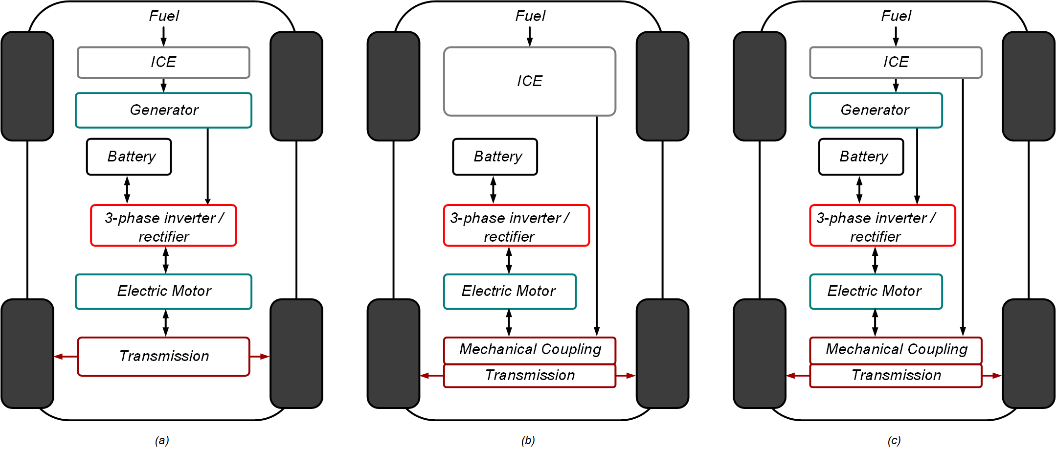
The main HEV architectures are series, parallel and combination of series and parallel, shown in Figure 2-1. In the series configuration (a), the ICE is indirectly tied to the transmission through the electric motor. The power electronics three-phase drive derives power from the ICE through the generator as well as from the battery. In this architecture, the ICE is optimized for a certain range of speed allowing for minimized size and increased efficiency. This is the simplest HEV architecture with regards to mechanical complexity since there is no coupling of mechanical energy.
The parallel HEV configuration (b) utilizes a combination of the ICE and electric motor mechanically coupled. The electric drive is primarily used as a low-power starter and alternator in this architecture, and is thus lower power. The efficiency of the ICE is lower due to the larger operating range but the size of the electric motor is minimized because it does not need to provide as much power as the ICE.
The series/parallel configuration (c) combines the two previous methods to achieve better efficiency. Mechanical coupling is performed by a planetary gear and the ICE and electric drives combine the traction power. In this case, the electric motor and ICE can be designed to operate within specified output ranges to improve their efficiency.
In each case, the three phase inverter is used to drive the electric motor. The inverter design varies based on the power output requirements which depends on architecture. The proper control of the inverter directly impacts the motor's efficiency and the overall efficiency of the vehicle.
 Figure 2-1 HEV Architectures
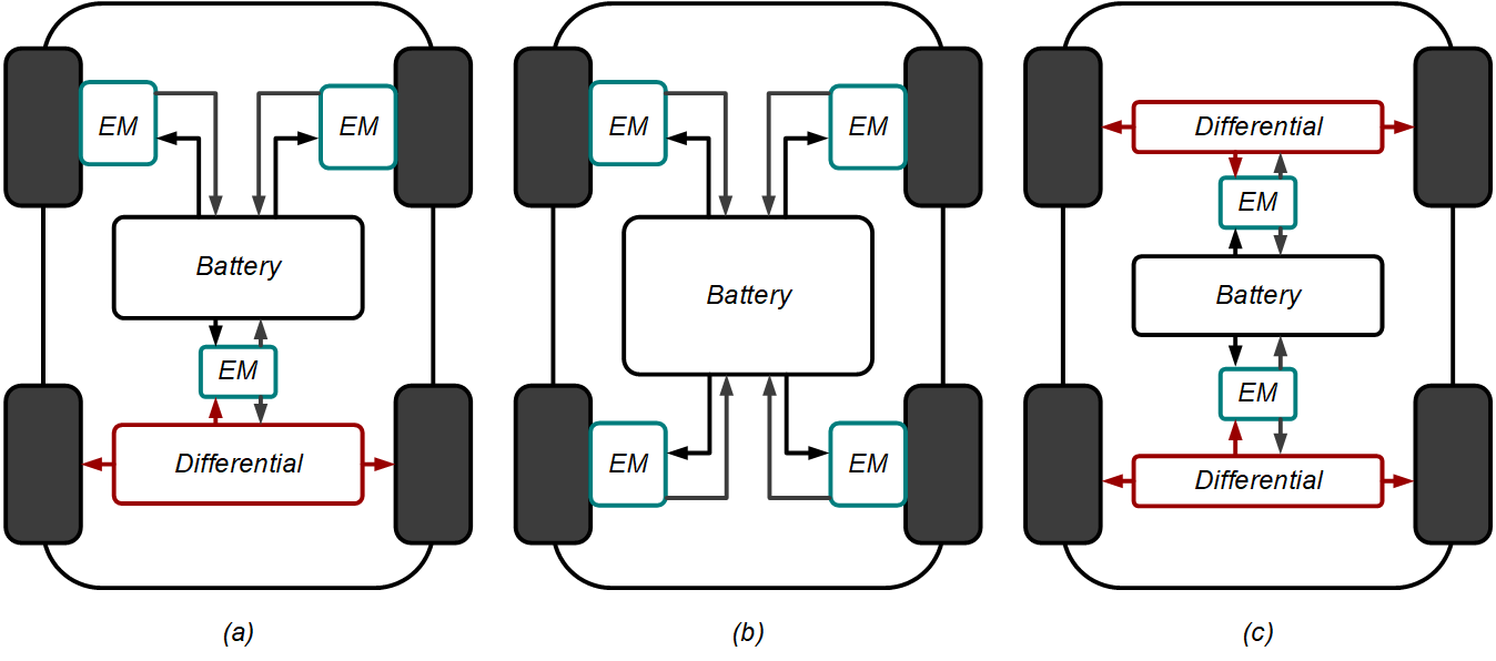
The pure electric vehicle, on the other hand, does not have an ICE and relies solely on the energy of the battery. Some different configurations of electric motor is shown in Figure 2-2. Similar to the HEV, each architecture results in different power requirements for the inverter. The electric motor may be directly tied to the wheel as shown in configurations (a) and (b) or tied to the wheel through a differential as shown in (a) and (c). Direct in-wheel drives has the benefit of simplicity and high efficiency with low maintenance, but must typically be larger in size due to low-speed requirements. The differential drive allows for high power density such that the motor can operate at a high RPM while the differential provides a fixed gear ratio. The drawback is that the mechanical gears require maintenance and has transmission loss.
High-voltage Li-ion batteries are commonly used as the energy storage unit to provide the maximum amount of capacity, minimal weight, and highest efficiency. With current technology, including various battery chemistries and power electronics efficiency, EVs still have limited range compared to HEV and plug-in HEVs. High performance EVs rely on increased power level of the traction inverter, minimization of the electronics' size, and complex controls based on sensed signals.
By increasing the efficiency and robustness of the inverter comes the increase of overall vehicle efficiency. The gate drivers makes an impact by providing the driving force behind each power switch in the inverter, as well as protection and monitoring to reduce the likelihood of failure.
 Figure 2-2 EV Architectures
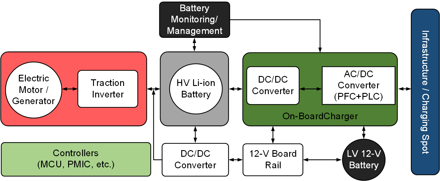
The key blocks of an EV powertrain system are the electric motor, the traction inverter drive, the DC/DC converter, the Li-ion battery, the AC/DC grid-tied on-board charger (OBC), and controllers (MCU and PMIC), as shown in Figure 2-3. The traction inverter system, highlighted in red, is described in detail in the following sections. This system alone incorporates many of the protection and monitoring features utilized to achieve high safety levels.
 Figure 2-3 Blocks within an EV
System