SLUUCF7 April 2021 BQ25960
2.2 Equipment Setup

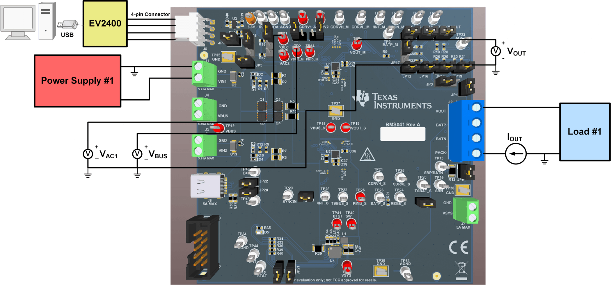
Figure 2-1 Equipment Test Setup
Use the following list to set up the EVM testing equipment. Refer to Figure 2-1 for the test setup connections to the EVM.
- Review the EVM connections in Table 1-2.
- Install jumpers as shown in Table 1-3.
- Set PS1 for 8.3 VDC, 1 A current limit, and then turn off the supply.
- Connect PS1 to J1 (VIN1 and GND).
- Connect a voltage meter across TP1 (VAC1) and TP37 (GND) to measure the input voltage as seen from the VAC1 bump of the U1 charger.
- Connect a voltage meter across TP2 (VBUS_M) and TP37 (GND) to measure the input voltage as seen from the VBUS bumps of the U1 charger.
- Set Load #1 to constant voltage mode with an output of 4.0 V, and then disable the load.
- Connect Load #1 to J2 (VOUT and PACK-). Connect a current meter in series to measure the output current, as shown in Figure 2-1.
- Connect a voltage meter across TP5 (VOUT_M) and TP37 (GND) to measure the output voltage as seen from the VOUT bumps of the charger.