SNLA113C november 2008 – june 2023 DS91M124 , DS91M125 , SN65LVDM050 , SN65LVDM050-Q1 , SN65LVDM051 , SN65LVDM051-Q1 , SN65LVDM1676 , SN65LVDM1677 , SN65LVDM176 , SN65LVDM179 , SN65LVDM180 , SN65LVDM22 , SN65LVDM31 , SN65MLVD040 , SN65MLVD047A , SN65MLVD048 , SN65MLVD080 , SN65MLVD082 , SN65MLVD128 , SN65MLVD129 , SN65MLVD2 , SN65MLVD200A , SN65MLVD202A , SN65MLVD204A , SN65MLVD204B , SN65MLVD206B , SN65MLVD3
- 1
- AN-1926 An Introduction to M-LVDS and Clock and Data Distribution Applications
- Trademarks
- 1 Introduction
- 2 M-LVDS Standard Overview
- 3 Driver Characteristics
- 4 Receiver Characteristics
- 5 M-LVDS Portfolio
- 6 M-LVDS Applications
- 7 Clock Distribution in AdvancedTCA Systems
- 8 Clock Distribution in MicroTCA Systems
- 9 M-LVDS as a Short Reach RS-485 Alternative
- 10Signal Distribution with Point-to-Point Links
- 11Wired-OR Implementation
- 12Design Guidelines
- 13Conclusion
- 14References
- 15Revision History
3 Driver Characteristics
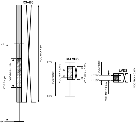
Per TIA/EIA-899 standard, an M-LVDS driver generates a differential signal with 480 – 650 mV amplitude and an offset within the 0.3V to 2.1V range. The signal must have 10% – 90% transition times (rise and fall) of 1 ns or greater and up to one half of a unit interval (tUI).
When compared to RS-485 drivers, M-LVDS drivers provide significantly reduced signal amplitudes (See Figure 3-1) that result in lower power consumption and reduced electromagnetic interference (EMI). The lower signal amplitudes enable higher signaling rates or signal frequencies. While the M-LVDS standard specifies maximum signaling rate of 500 Mbps based on the 1 ns minimum transition time, current commercially available M-LVDS drivers peak at 250 Mbps. On the other side, the fastest RS-485 drivers typically peak at 10 Mbps with a few unique devices reaching 30 Mbps to 50 Mbps rates. The benefits of faster speeds, lower power, and reduced EMI come at the expense of reduced noise margins, however, by following necessary design guidelines given later in this application note, successful M-LVDS networks can be designed without significant efforts.
 Figure 3-1 Driver VOD and VOS
Comparison
Figure 3-1 Driver VOD and VOS
ComparisonWhen compared to LVDS drivers, M-LVDS drivers pose as drivers with a stronger drive (larger IOD). The stronger drive enables the M-LVDS drivers to drive signals across multipoint networks that are typically doubly terminated. Doubly terminated networks present a heavier load to the driver, so the stronger drive is necessary for retaining required signal amplitudes. Both M-LVDS and RS-485 driver output amplitudes are typically specified with a 50Ω differential load. This is a load that a driver typically sees in a multipoint network with a double termination as illustrated in Figure 2-1. LVDS driver output amplitudes are specified with a 100Ω differential load. This is a load that a driver typically sees in a point-to-point link with a single termination as shown in Figure 3-2. M-LVDS drivers also pose as drivers with controlled transition times, a characteristic that is highly desirable for multipoint networks. On the other side, LVDS drivers with transition times typically ranging from as low as 100 ps to only several 100 ps are rarely a good fit for any topology except a point-to-point topology.
 Figure 3-2 Point-to-Point Link
Table 3-1 shows a comparison of key RS-485, M-LVDS, and LVDS driver characteristics:
| Parameter | RS-485 | M-LVDS | LVDS |
|---|---|---|---|
| VOD (V) | 1.5 to 5.0 | 0.48 to 0.65 | 0.25 to 0.45 |
| VOS (V) | -1.0 to 3.0 | 0.3 to 2.1 | 1.125 to 1.375 |
| IOD (mA) | 28 to 93 | 9 to 13 | 2.5 to 4.5 |
| IOS (mA) | <250 | <43 | <24 |
| tRISE / tFALL Min (ns) | N/A | 1 | N/A |
| tRISE / tFALL Typ (ns) | 5 to 50 | 1 to 5 | <1 |
| tRISE / tFALL Max (ns) | 0.3 tUI | 0.5 tUI | 0.3 tUI |
| Typ Data Rate (Mbps) | DC to 10 | DC to 500 | DC to 3125 |