SSZTAM5 november 2016 UCC27211A , UCC27524A , UCC27714
We live in a world where designers are on a seemingly constant pursuit for higher efficiency. We want more power out with less power in! Higher system efficiency is a team effort that includes (but is not limited to) better-performing gate drivers, controllers and new wide-bandgap technologies.
Specifically, high-current gate drivers can help facilitate overall higher system efficiency by minimizing switching losses. Switching losses occur when a FET switches or turns on and off. To turn a FET on, the gate capacitance must be charged beyond the threshold voltage. The drive current of a gate driver facilitates the charging of the gate capacitance. The higher the drive-current capability, the faster the capacitance can charge or discharge. Being able to source and sink a large amount of charge minimizes power losses and distortion. (Conduction loss is the other type of switching loss in FETs. Conduction losses are defined by the internal resistance, or RDS(on), of the FET where . The FET dissipates power as current is conducted through.)
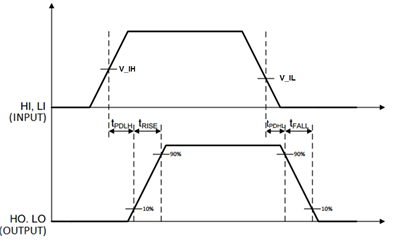
In other words, the goal is to minimize the switching transition time period in systems that require high-frequency power conversion. The gate-driver specification that highlights this type of performance is the combined rise and fall time. See Figure 1.
 Figure 1 Typical Rise and Fall Time
Diagram
Figure 1 Typical Rise and Fall Time
DiagramIf you want to take it up a notch, gate-driver features like delay matching can effectively double the drive-current capability. Delay matching is the matching of internal propagation delays between two channels. This is achieved by paralleling the outputs, or tying the channels together, of dual-channel gate drivers. For example, TI’s UCC27524A has extremely accurate 1ns (typical) delay matching, which can increase the drive current from 5A to 10A.
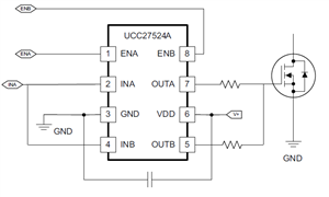
Figure 2 shows the UCC27524A’s A and B channels combined into one driver. The INA and INB inputs are connected together, as are OUTA and OUTB. One signal controls the paralleled combination.
 Figure 2 The UCC27524A with Paralleled
Outputs to Double Drive-current Capability
Figure 2 The UCC27524A with Paralleled
Outputs to Double Drive-current CapabilityOne result of increased system efficiency is an increase in power density. The need for higher power densities is a trend in applications like power factor correction (PFC) and synchronous rectification blocks of isolated power supplies, DC/DC bricks and solar inverters, where designers are constrained to the same size (or smaller!) for the same amount of output power.
TI’s portfolio includes gate drivers with high current, fast rise and fall times, and delay matching. See Table 1.
| Category | Device | Description | Rise/fall time | Delay matching |
|---|---|---|---|---|
| High-current drivers | UCC27714 | 4A, 600V high- and low-side driver | 15ns, 15ns | Yes |
| UCC27524A | 5A, high-speed low-side dual driver | 7ns, 6ns | Yes | |
| UCC27211A | 4A, 120V high- and low-side driver | 7.2ns, 5.5ns | Yes |
Get started on your high-efficiency system today. For more info, see www.ti.com/gate drivers.
Additional Resources
- These TI Designs showcase high-current gate drivers in high-efficiency systems: