SWRA486A August 2015 – April 2017 CC1310 , CC2620 , CC2630 , CC2640 , CC2640R2F-Q1 , CC2650 , CC2650MODA
- CC26x0, CC13x0 SimpleLink™ Wireless MCU Power Management Software Development
-
CC26x0, CC13x0 SimpleLink™ Wireless MCU Power Management Software Development
- 1 Abbreviations
- 2 Power Management Introduction
- 3 TI-RTOS Power Modes
- 4 Implementation Considerations
- 5 References
- Revision History
3.3.1 Standby Enter Sequence
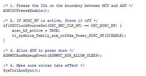
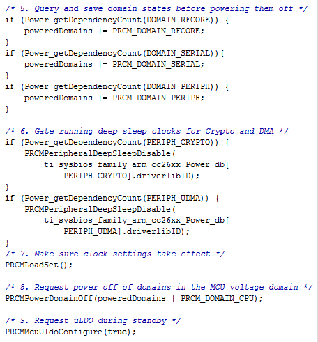
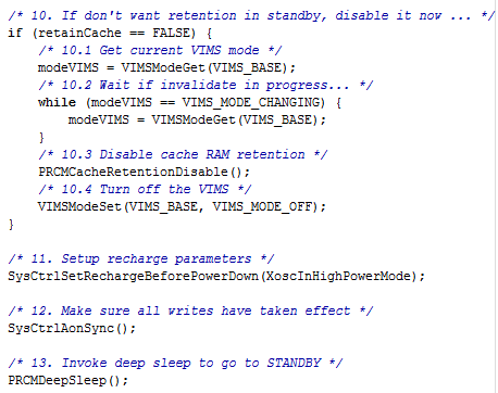
Figure 2, Figure 3, and Figure 4 show the code sequence for taking the device into standby mode. A brief explanation of each step is also provided.
 Figure 2. Standby Enter Sequence, Part 1
 - Freeze the IOs on the boundary between MCU and AON– Latch (freeze) the input and output pins to avoid glitches when in standby. When the inputs and outputs are frozen, the current state of the inputs and outputs is retained while available to trigger wakeup to the Cortex-M3. To configure the inputs for wakeup from standby, see Section 4.4.1.
- If XOSC_HF is active, force it off– Turn off the high-speed crystal oscillator before entering standby. The hardware turns off the high-speed RC oscillator when entering standby. For details on how to configure the high-speed crystal oscillator, see Section 4.5.1.
- Allow AUX to power down– Disconnect the auxiliary domain from the MCU in standby.
- Make sure writes take effect– Ensure the writes to AON domain complete before continuing.
- Query and save domain states before powering them off– Turn off all power domains before entering standby.
- Gate running deep sleep clocks for Crypto and DMA– Clear both the crypto and DMA deep-sleep clock enable bits before entering standby. For more information, see the PRCM:VDCTL register.
- Make sure clock settings take effect– Load the clock settings from the PRCM module.
- Request power off of domains in the MCU voltage domain–Turn off power domains inside the MCU voltage domain.
- Request uLDO during standby– Use this call to request to use the micro-LDO during standby. The system runs off the micro-LDO in standby.
 Figure 3. Standby Enter Sequence, Part 2
  Figure 4. Standby Enter Sequence, Part 3
 10. If don't want retention in standby, disable it now...– Disable cache retention and turn off the VIMS power domain to achieve lowest power consumption in standby.
10.1 Get current VIMS mode– Read the current VIMS mode.
10.2 Wait if invalidate in progress...– Ensure that the VIMS mode remains the same.
10.3 Disable cache RAM retention– Disable cache RAM retention.
10.4 Turn off the VIMS– Set the VIMS mode to off. The cache is off and the Cortex-M3 reads instructions from flash.
11. Setup recharge parameters– Configure safe recharge settings used when in standby. A XoscInHighPowerMode flag indicates that the high-frequency crystal oscillator is off in standby.
12. Make sure all writes have taken effect— Ensure all AON writes have taken effect.
13. Invoke deep sleep to go to STANDBY— Put the Cortex-M3 in deep-sleep through the WFI instruction to enter standby.