DLPU126 December 2023 DLP470TE , DLP660TE , DLP780TE , DLPC4420
- 1
- Description
- Getting Started
- Features
- 5
- 1Evaluation Module Overview
- 2Hardware
- 3Software
- 4Hardware Design Files
- 5Additional Information
- 6Related Documentation from Texas Instruments
3.1.2 Powering-up the DLPC4420AEVM and Preparing for the DLPC4420AEVM to be Programmed
Before powering up the EVM, make sure the included DLPC4420AEVM jumpers are in the correct positions. The jumper locations are listed in Table 4-1.
| Jumper | Description (Bold Indicates Default Position) |
|---|---|
| J11 - Front end 12 V | Uninstalled - main board is powered from the AC adapter Installed - Front end board provides power to main board |
| J14 - Blue LED enable or lamp ballast | Pins 1,2 connected Blue LED Enable Pins 2,3 connected Lamp mode |
| J28 - TDO1 or TDO2 | Pins 1,2 connected TDI in to secondary is from TDO1 from Primary Pins 2, 3 connected TDI in to secondary is from TDO2 from Primary |
| J29 - Manual reset | Uninstalled - Normal operation Installed - Hold in reset |
| J31 - Hold in boot loader | Uninstalled - Normal operation Installed - Hold in boot loader |
| J32 - Vx1 Swap P/N | Uninstalled - Swapping P and N Installed - Not swapping P and N |
| J33 - Vx1 swap bit order | Uninstalled - Swapping Bit Order Installed - Not swapping bit order |
| J34 - LED enable invert | Pins 1, 2 connected LED_EN inverted Pins 2, 3 connected LED_EN not inverted |
| J38 - Light to frequency sensor or ADC integrating sensor | Pins 1,2 connected ADC integrating sensor Pins 2,3 connected Comparator Sensor |
| J40 - High current Fan 5 or Fan 6 | Pins 1,2 connected for high current fan 5 Pins 2, 3 connected for fan 6 |
Jumper J31 is the Hold BL jumper. This jumper is used to put the DLPC4420AEVM into boot loader mode, which allows the DLPC4420 controllers to be programmed. Connect this jumper to prepare the DLPC4420AEVM to be programmed.
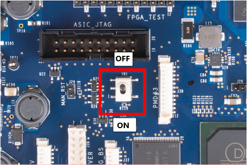
To power up the DLPC4420AEVM, a 12 V, 5 A power supply is needed. Make sure the power supply is functional and the switch SW1 on the EVM is set to off before connecting the power supply to the EVM. Connecting the power supply when the switch is in the off position can prevent damage to the DLPC4420AEVM from poor power connections. The image below shows SW1 in the on position.
 Figure 3-1 ON/OFF Switch
Once the power supply has been connected to the DLPC4420AEVM, the switch SW1 can be flipped to the on position. You can then plug in the USB cable into the board to prepare for programming the board.