SBAA274A September 2018 – March 2023 ADS1118 , ADS1119 , ADS1120 , ADS112C04 , ADS112U04 , ADS1146 , ADS1147 , ADS1148 , ADS114S06 , ADS114S06B , ADS114S08 , ADS114S08B , ADS1219 , ADS1220 , ADS122C04 , ADS122U04 , ADS1246 , ADS1247 , ADS1248 , ADS124S06 , ADS124S08 , ADS125H02 , ADS1260 , ADS1261 , ADS1262 , ADS1263
- A Basic Guide to Thermocouple Measurements
- Trademarks
- 1Thermocouple Overview
-
2Thermocouple Measurement Circuits
- 2.1 Thermocouple Measurement With Pullup and Pulldown Bias Resistors
- 2.2 Thermocouple Measurement With Biasing Resistors Attached to the Negative Lead
- 2.3 Thermocouple Measurement With VBIAS for Sensor Biasing and Pullup Resistor
- 2.4 Thermocouple Measurement With VBIAS For Sensor Biasing and BOCS
- 2.5 Thermocouple Measurement With REFOUT Biasing and Pullup Resistor
- 2.6 Thermocouple Measurement With REFOUT Biasing and BOCS
- 2.7 Thermocouple Measurement With Bipolar Supplies And Ground Biasing
- 2.8 Cold-Junction Compensation Circuits
- 3Summary
- 4Revision History
1.2.3 Thermocouple Construction
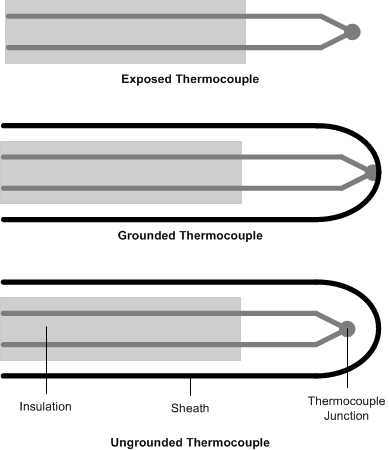
Thermocouples come in several different construction types as shown in Figure 1-3. Thermocouple leads are protected by a layer of insulation and often have a protective sheath at the thermocouple junction tip to protect the sensor element.
 Figure 1-3 Thermocouple Construction Types
A thermocouple without a protective sheath is known as an exposed thermocouple. This allows for a small sensor, with direct heat transfer from the measured object. This type of thermocouple gives a fast sensor response.
In a grounded thermocouple, the sensor is welded to the sheath. Often this sheath is composed of metal, which also allows for heat transfer, but adds an extra protection for harsh and difficult environments. However, because the thermocouple is welded to the metal sheath, there is electrical contact. This makes the measurement susceptible to noise from ground loops.
An ungrounded thermocouple is isolated from the sheath, adding a layer of insulation between the thermocouple the measured object. This type of thermocouple has the slowest of the temperature responses because there is an isolation layer.
As mentioned, both grounded and exposed thermocouples have faster temperature responses because of the excellent heat transfer of metal contact. However, with direct metal contact there is electrical contact between the measurement circuit and anything the thermocouple contacts. This may cause ground loop problems with the measurement.
If the ground of the circuit is at a different electrical potential than the contact from the thermocouple, then the measurement circuit may be disrupted. As an example, a grounded or exposed thermocouple may contact earth ground, which may not be the same as the ADC ground. This can cause a variety of problems, including bad measurement data or even damage to the circuit. Even if the earth ground and ADC ground are identical, the thermocouple may not be in the range of the PGA. When using an exposed or grounded thermocouple, ensure that the thermocouple contact does not disrupt signal or measurement integrity.