SBAA274A September 2018 – March 2023 ADS1118 , ADS1119 , ADS1120 , ADS112C04 , ADS112U04 , ADS1146 , ADS1147 , ADS1148 , ADS114S06 , ADS114S06B , ADS114S08 , ADS114S08B , ADS1219 , ADS1220 , ADS122C04 , ADS122U04 , ADS1246 , ADS1247 , ADS1248 , ADS124S06 , ADS124S08 , ADS125H02 , ADS1260 , ADS1261 , ADS1262 , ADS1263
- A Basic Guide to Thermocouple Measurements
- Trademarks
- 1Thermocouple Overview
-
2Thermocouple Measurement Circuits
- 2.1 Thermocouple Measurement With Pullup and Pulldown Bias Resistors
- 2.2 Thermocouple Measurement With Biasing Resistors Attached to the Negative Lead
- 2.3 Thermocouple Measurement With VBIAS for Sensor Biasing and Pullup Resistor
- 2.4 Thermocouple Measurement With VBIAS For Sensor Biasing and BOCS
- 2.5 Thermocouple Measurement With REFOUT Biasing and Pullup Resistor
- 2.6 Thermocouple Measurement With REFOUT Biasing and BOCS
- 2.7 Thermocouple Measurement With Bipolar Supplies And Ground Biasing
- 2.8 Cold-Junction Compensation Circuits
- 3Summary
- 4Revision History
1.4.6 Burn-out Detection
If a thermocouple has failed or burned out, system designers may want to some indication that this has occurred. A full-scale ADC reading for an opened sensor can be used to help make this determination. This measurement may be part of a normal measurement or the system may require an interim measurement as a periodic check.
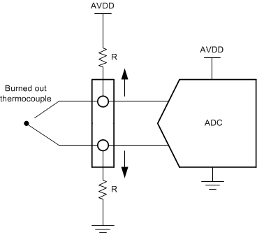
Methods of thermocouple biasing can allow for automatic burn-out detection. As an example, when the thermocouple is biased through resistors attached from each thermocouple lead to either supply shown in Figure 1-9. The small resistor currents hold the thermocouple at a DC bias point if the thermocouple is intact and produces a small voltage. If the thermocouple has burned out and become high impedance, the resistors pull the voltage of each lead to either rail. This would cause the ADC input to be greater than the full-scale range and cause the ADC to give a full-scale reading (7FFFh for a 16-bit ADC). Again, the resistors should be small enough to overcome the input bias current of the ADC.
 Figure 1-9 Burn-out Detection Using Resistor Biasing
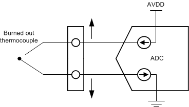
In different methods of thermocouple biasing, there may be no pullup resistor to enable a burn-out measurement. Many precision ADCs include burn-out current sources (BOCS), where a current source is used to pull up on the positive analog input and a current sink pulls down on the negative analog input as shown in Figure 1-10. These current sources are used to pull apart the positive and negative leads of a thermocouple during a burn-out condition. This is useful even if the thermocouple is biased from only one end by a DC source, such as a reference voltage or VBIAS line. The positive burn-out current source pulls the positive lead high enough so that the ADC reads a positive full-scale reading.
 Figure 1-10 Burn-out Detection Using BOCS
In general, the burn-out measurement using BOCS should be a separate measurement than the normal temperature measurement. Using the BOCS may induce error when the thermocouple is not burned out. Extra current may lead to self-heating of the sensor. Additionally, there are often RC filters at the front end of the ADC. Because the BOCS are sourced from the device, additional current flowing from BOCS creates an error voltage as they pass through the series filter resistors.
When enabling the BOCS for a burn-out measurement, ensure that there is additional time for voltage setting between measurements. Filter capacitance may require time for voltage settling in both the burn-out and temperature measurement.