SLUU070A December 2001 – June 2021 TPS62100 , TPS62101 , TPS62102 , TPS62103
3 Feedback Considerations
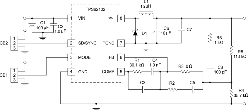
Figure 3-1 shows the gain and phase response for the internal error amplifier. In addition to thecompensation configuration used, many other feedback configurations are provided for on the evaluation module by using the optional component footprints. Figure 3-1 shows the schematic of the evaluation module with these additional footprints. As is evident, most any common feedback implementation can be achieved by simply shorting across pads or inserting passive components. The extra footprints are all 1206 size for ease of use.
 Figure 3-1 Complete Evaulation Module Schematic