SNAU210B March 2020 – July 2021
- Trademarks
- 1Evaluation Board Setup
- 2EVM Description
- 3Bringing LMX2594 to a Lock State
- 4Loop Filter Configuration
- 5Key Results to Expect
- A Schematic
- B Bill of Materials
- C Board Layers Stack-Up
- D Changing Reference Oscillator and Setup
- E Connecting Reference Pro
- F Ramping Feature
- G SYSREF Feature
- H Enabling Onboard DC-DC Buck Converter (TPS62150)
- Revision History
D Changing Reference Oscillator and Setup
The reference can be single-ended or differential. To measure the performance of the PLL ONLY, the reference should have at least this level of performance. We understand that this can be a challenge at 100-Hz offset:
Table D-1 Reference Oscillator
Requirements
| 100-MHz REFERENCE MINIMUM REQUIREMENTS FOR A 0.4-dB IMPACT ON PLL INBAND PN(1) | ||||
|---|---|---|---|---|
| Offset [Hz] | 100 | 1k | 10k | 100k |
| Noise level [dBc/Hz] | –139 | –149 | –159 | –164 |
(1) A noise source 10 dB down from the PLL noise will contribute to
raise the noise by 0.4 dB.
There are different options to provide a reference oscillator to LMX2594. Use on-board oscillator, enable LMK61xx from Reference Pro PCB, or use external oscillator. By default, the EVM is configured for an external single-ended clock.
Table D-2 Reference Clock Input
Configuration
| INPUT | EXTERNAL CLOCK | CRYSTAL OSCILLATOR |
|---|---|---|
| Single-ended | 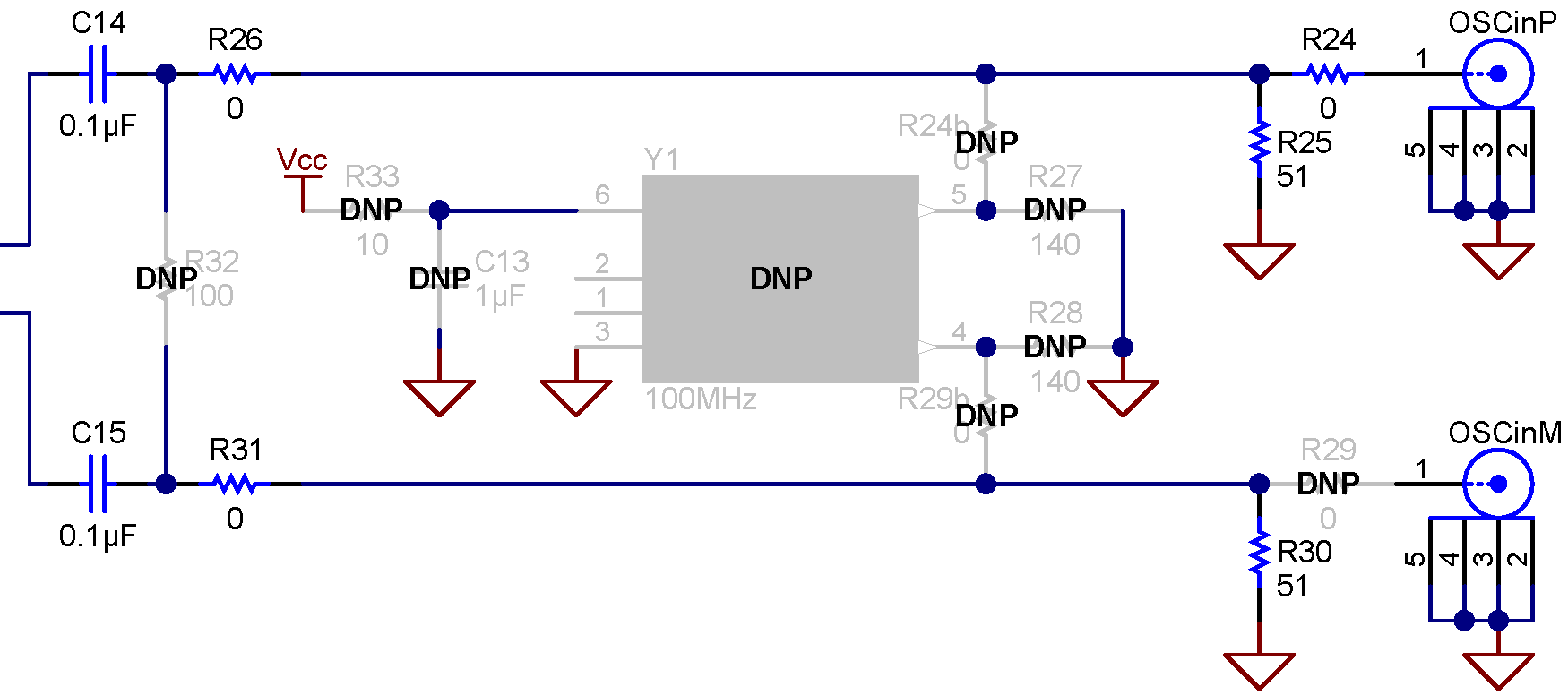 |
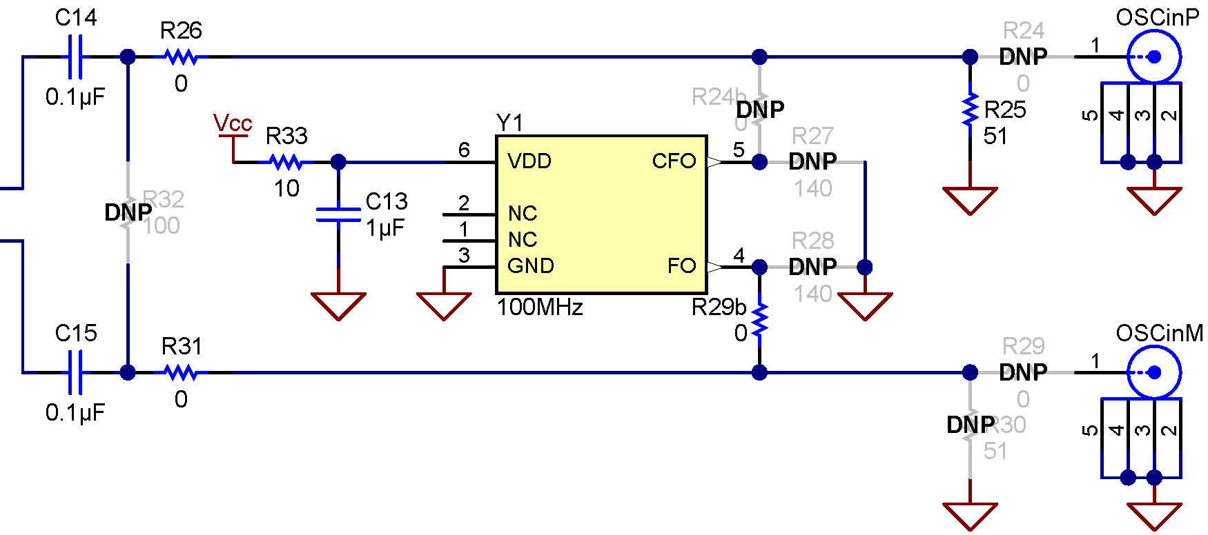 |
| Differential (LVDS) |
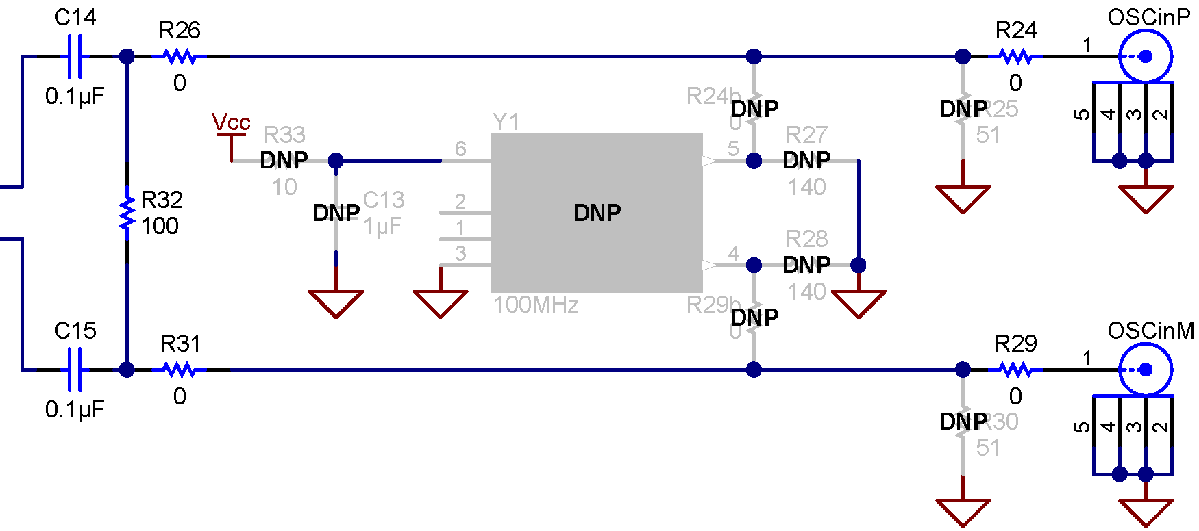 |
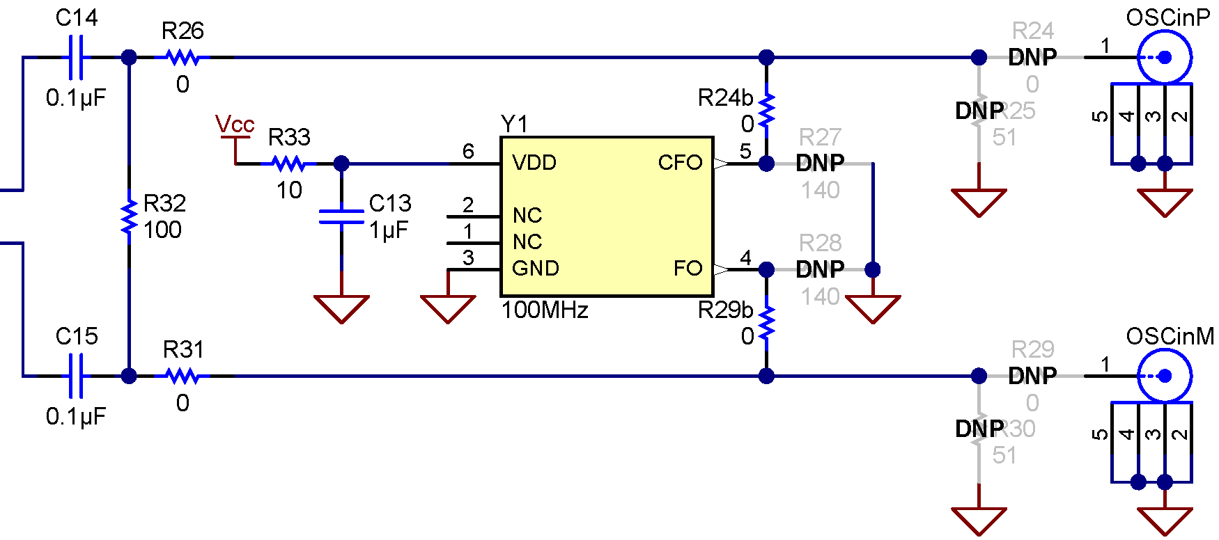 |