SNLA423 March 2023 DP83826E
- 1Trademarks
- 2DP83826 Application Overview
- 3Troubleshooting the Application
- 4Conclusion
- 5Revision History
3.4.6 Probe the MDI Signals
In the default configuration, Auto-negotiation and Auto-MDIX will be enabled. A link pulse should be visible on the channel transmit and receive differential pair (TD_P, TD_M).
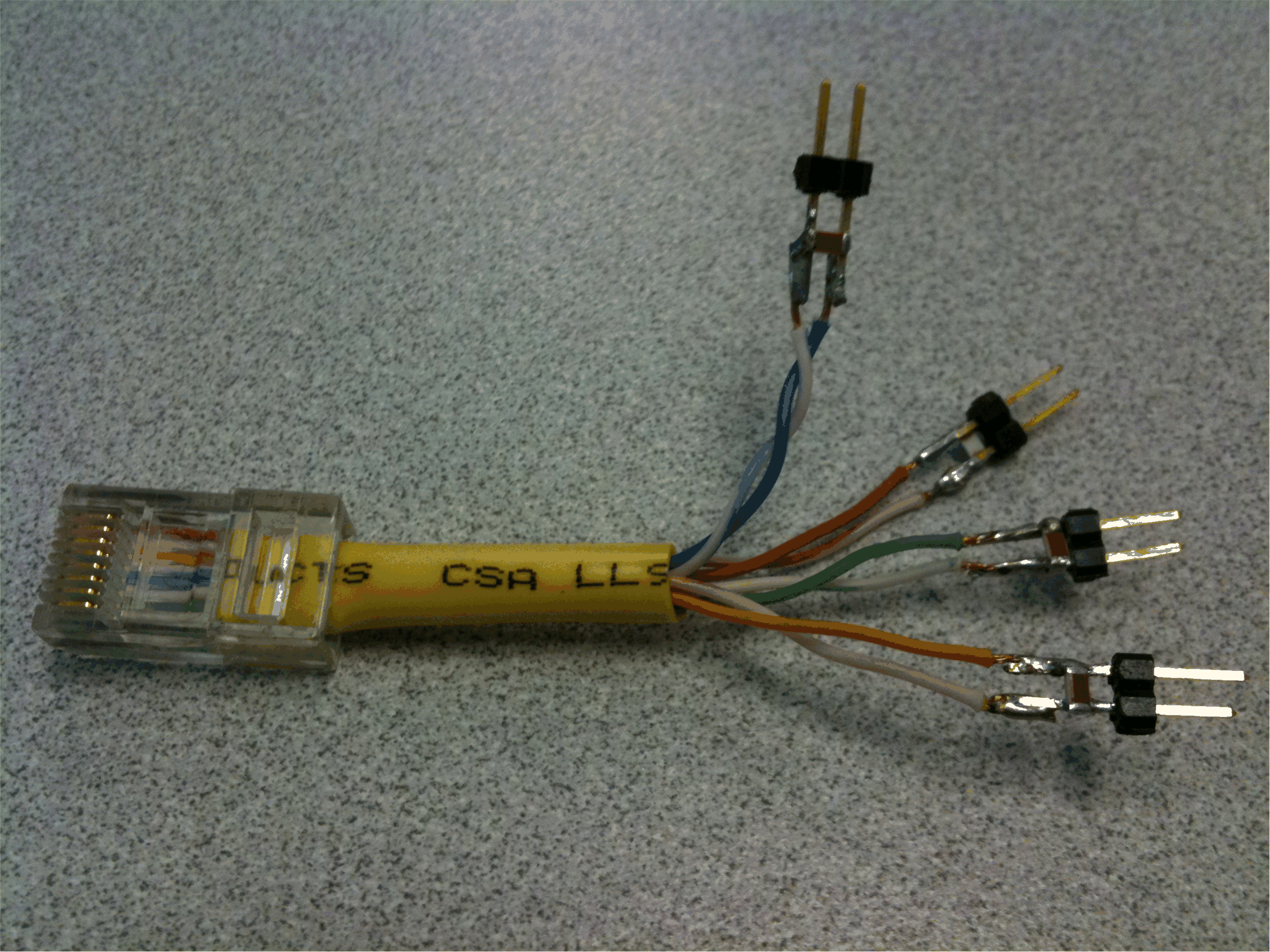
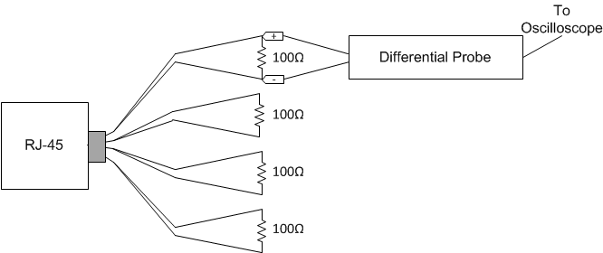
A short Ethernet cable with 100 Ohm terminations can be used for measuring the MDI signals. A terminated cable is shown in Figure 3-2. A connection diagram for making measurements with the terminated cable is shown in Figure 3-3.
 Figure 3-2 100 Ω Terminated Cable
for MDI Signal Measurement
 Figure 3-3 Connection Diagram for
100 M Terminated Cable
Figure 3-3 Connection Diagram for
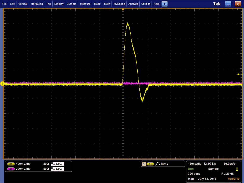
100 M Terminated CableAuto-Negotation link pulses are nominally 100ns wide. Pulses are spaced by 62 µs or 125 µs and are transmitted in bursts. The bursts are nominally 2 ms in duration and occur every 16 ms. Figure 3-4shows a link pulse.
 Figure 3-4 DP83826 Link Pulse