SSZTBA4 may 2016 SN65HVD72 , SN65HVD75

Welcome back to the “Get Connected” blog series on Analog Wire. In my previous post, I explored protecting your differential bus against system-level transients using a transient voltage suppressor (TVS) diode and pulse-proof resistors. In this post, I’ll take a look at the pros and cons of operating a RS-485 link without any termination on the bus.
Before diving into the topic of an unterminated RS-485 bus, let’s review the basics of traditional RS-485. The Telecommunications Industry Association/Electronic Industries Alliance (TIA/EIA)-485-A is a balanced data-transmission standard for serial communication. RS-485 provides robust serial data transmission at moderate data rates over long distances in multipoint communication applications. Traditionally, an RS-485 bus is connected in a daisy-chain fashion, supports up to 32 nodes on a single bus, has a 60Ω characteristic bus impedance and is terminated with a 120Ω resistor at each end of the network to match the characteristic impedance of the bus. Figure 1 shows a traditional half-duplex RS-485 bus topology.
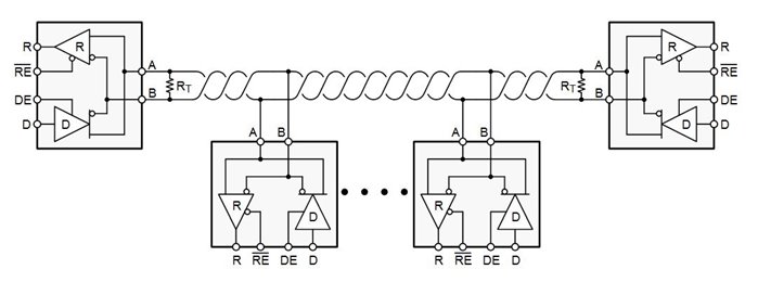 Figure 1 Traditional Half-duplex RS-485
Bus Topology
Figure 1 Traditional Half-duplex RS-485
Bus TopologyInstalling termination in the proper locations can be troublesome in applications like building automation, where you may not know the two farthest nodes. Additionally, the technician performing the installation may not have a clear understanding of termination, why it is important, or how unterminated stubs can lead to signal-integrity issues that cause network downtime.
The workaround for a problem like this is not to train all of the technicians in the world in the finer points of RS-485, but rather to eliminate the termination. Figure 2 shows an unterminated half-duplex RS-485 bus topology.
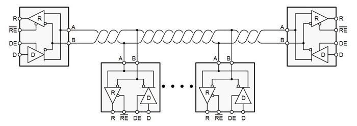 Figure 2 Unterminated Half-duplex
RS-485 Bus Topology
Figure 2 Unterminated Half-duplex
RS-485 Bus TopologyAt this point, you may be asking how an RS-485 bus can operate successfully without termination. The answer is in the driver stage of the RS-485 transceiver. An RS-485 transceiver employs a full H-bridge output structure that is designed to drive a minimum of 1.5V differentially across a 54Ω load. The bus voltages for RS-485 are typically VOH = 3.5V and VOL = 1.5V, with a common-mode voltage (VCM) of 2.5V. This does vary from device to device, which is why these values are stated as typical.
When there is no termination present on the bus, the output stage of the transceiver still switches normally with the incoming data on the driver. But instead of swinging from the typical VOH and VOL, the output will swing full rail (from VCC to GND) minus a diode drop. The design of the output stage includes the diode for reverse-current protection on the device.
Nothing is free, though, and there is a drawback to eliminating termination on the RS-485 bus. When termination is removed, the entire bus acts essentially as a giant stub, causing bandwidth limitation in the design. Stubs on a bus cause reflections – and reflections cause signal-integrity issues that lead to data-communication errors. How long a stub can be in a design is not dependent on data rate, but rather the transition time from high to low and vice versa.
You can calculate the maximum stub length achievable in a design using Equation Figure 3:
 Figure 3 (1)
Where v is signal velocity of the cable as a factor of c (typically 78% for copper) and c is the speed of light. From Equation Figure 3, you can see that the slower the transition time of the RS-485 transceiver, the longer the stub can be.
To illustrate the above point, I used the SN65HVD72 with a typical rise time (tr) of 700ns and the SN65HVD75 with a tr of 7ns. I tested both devices at 250kbps on a short bus (~8 inches) with a 10-foot stub. The 10-foot stub dominants the performance of this test case. Figure 4 depicts a visual representation of the topology used for this test case. Figure 5 and Figure 6 below show the results from the SN65HVD72 and SN65HVD75 test case respectively.
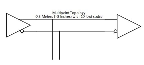 Figure 4 Unterminated Bus
Topology
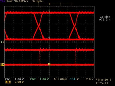 Figure 5 SN65HVD72 Output Bus
Waveform
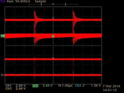 Figure 6 SN65HVD75 Output Bus
Waveform
Figure 6 SN65HVD75 Output Bus
WaveformFrom this test data, you can conclude that with careful selection of the RS-485 device, you can eliminate the termination resistors from some buses, and thus remove the need to know the farthest reaches of the bus. This takes the guesswork out of installation for technicians and ultimately accelerates the implementation of the end customer solution. Results will vary from design to design, as the type of bus topology (star network, cluster network design, or linear daisy chain) will play a factor in system performance.
Leave a comment below if you’d like to hear more about anything discussed in this post, or if there is an interface topic you’d like to see in the future. You can also subscribe to Analog Wire to receive an email notification upon the publication of the next post.
Additional Resources
- Get online support in the TI E2E™ Community Interface forum.
- Learn more about RS-485 tools and software.
- Read more posts in the “Get Connected” series.