SSZTBW4 november 2015
So far in this series, we have discussed various digital-interface options for motor position encoders including EnDat 2.2, bidirectional/serial/synchronous (BiSS) and HIPERFACE DSL.
These are the main standards using RS-485- or RS-422-based serial digital interfaces to connect an absolute-position encoder. Further interface standards include Profibus Decentralized Peripherals (DP) and Profibus Input/Output (I/O), as well as controller-area network (CAN) or Ethernet-based interfaces. There are also proprietary, drive vendor-specific standards like DRIVE-CLiQ from Siemens, Fanuc serial interface, Mitsubishi high-speed serial interface and more. In this blog series, we’ve only covered EnDat, BiSS and HIPERFACE. In this post, I will summarize all the standards and share an EMC-compliant design that can support whichever standard you are implementing in your industrial drive.
Table 1 is an attempt to summarize the specs of all of these encoder interface standards, comparing three standards (EnDat 2.2, HIPERFACE DSL and BiSS) with regard to physical layer (PHY) and supply voltage. Figure 1 is an overview of the maximum clock frequency vs. cable length.
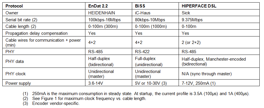 |
 Figure 1 Maximum Clock Frequency vs.
Cable-length Specifications from 0 to 100m
Figure 1 Maximum Clock Frequency vs.
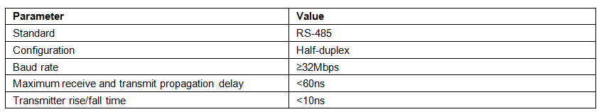
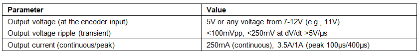
Cable-length Specifications from 0 to 100mTable 2 lists the basic specifications for the RS-422/RS-485 transceiver and for the power supply applicable to the three standards mentioned in Table 1. Table 3 shows the supply specifications for the same.
 |
 |
A Solution for the Absolute Position-encoder Interface
The Universal Digital Interface to Absolute Position Encoders Reference Design (TIDA-00179) implements an electromagnetic compatibility (EMC)-compliant universal digital interface to absolute-position encoders like EnDat 2.2, BiSS or HIPERFACE DSL.
The major building blocks of this TI Designs reference design are:
- A bidirectional four-wire RS-485 interface and two-wire bidirectional RS-485 interface with power over RS-485.
- A multiplexer or demultiplexer to select the active encoder interface.
- The encoder power supply with programmable output voltage and overvoltage, overcurrent and short-circuit protection.
- A 3.3V digital interface to a host processor to run the corresponding encoder standard protocol.
The host processor that runs the corresponding encoder master protocol is not part of this design.
Figure 2 shows a simplified system block of a universal digital interface module as a subsystem of an industrial drive to connect to absolute, with the reference design represented by the light-green box.
 Figure 2 Industrial Drive with
Universal Digital Interface to Absolute-position Encoders
Figure 2 Industrial Drive with
Universal Digital Interface to Absolute-position EncodersThe design is powered by an industry-standard 24V supply and features a wide-input voltage range from 15V to 60V. A connector with 3.3V logic I/O signals allows for a direct interface to the host processor like a Sitara™ AM437x or C2000™ microcontroller unit (MCU) to run the corresponding encoder’s master protocol. The C2000 MCU offers the DesignDRIVE development platform, as well as TIDM-SERVODRIVE that can be adapted to interface with a host port interface and TIDA-00179. The design allows the host processor to activate either the four-wire RS-485 physical interface to connect to an EnDat 2.2 or BiSS encoder, or the two-wire RS-485 interface with power over RS-485 to connect to a HIPERFACE DSL encoder.
To meet the selected encoder's supply ranges and specifications, the protected encoder power supply features a programmable output voltage of either 5.25V or 11V. We chose the voltage along with the voltage ripple and output current to ensure compliance with the overall supply specification for EnDat 2.2, BiSS and HIPERFACE DSL encoder standards. The encoder supply is also protected against short circuit, and the overvoltage threshold is matched to the selected output voltage with fault feedback.
You can connect the absolute-position encoder to the reference design either through a Sub D-15 connector or a 10-pin header. The connector has dedicated pins for connecting a two-wire HIPERFACE DSL encoder, which includes power over RS-485 and shared pins for EnDat 2.2 and BiSS position encoders. This design supports cable lengths of up to 100m. For cable specifications, see the corresponding encoder vendor’s recommendations.
The design has been tested for EMC immunity against electrostatic discharge (ESD), electrical fast transient (EFT), surge and conducted radio frequency (RF), with levels specified per IEC 61800-3.
To run the TIDA-00179, a hardware and a software layer is required. The master control is normally performed by an FPGA; this design uses the AM437x host processor to run all the three encoder protocols.
Like the TIDA-00179 hardware that combines the three designs for EnDat 2.2 (TIDA-00172), BiSS C (TIDA-00175) and HIPERFACE DSL (TIDA-00177), the new software provided with the AM437x combines the three software designs associated to them— the TIDEP0050 (EnDat 2.2), the TIDEP0022 (BiSS C) and the TIDEP0035 (Hiperface DSL)— in order to interface to any encoder that complies to any of the three major standards discussed in this blog series.
The TI Sitara AM437x provides integrated solution for single-chip drive and modular architecture using industrial Ethernet in parallel. It provides a register-compatible implementation to existing FPGA IP core. Internal and external synchronization with drive applications are available, with no host CPU load needed to run any of the three master protocols.
For more information and also to see the live demo, please visit TI booth at the SPS tradeshow in Nuremberg Nov. 24 to 26. The demo will show on-the-fly detection and connection to different position encoder protocols.
 Figure 3 Multiprotocol Position Encoder
Demo at SPS
Figure 3 Multiprotocol Position Encoder
Demo at SPSThis post concludes our series about designing an EMC-compliant interface to motor-position encoders.
If you would like to see other topics related to position-encoder interface design addressed in future blog posts, please comment below.
Additional Resources
- Check out this TI Designs reference design for a universal digital interface.
- Check out Sitara processor-based reference designs for EnDat, BiSS and HIPERFACE.
- Read other blogs on designing industrial EMC-compliant interfaces to motor-position encoders.
- Learn more about TIDM-SERVODRIVE design or watch an overview video.
- Visit TI’s booth at SPS in Nuremberg from Nov. 24 - 26 at booth 6-441.