TIDUED6B august   2018  – april 2023


  1.   Description
  2.   Resources
  3.   Features
  4.   Applications
  5.   Design Images
  6. 1System Description
    1. 1.1 Key System Specifications
  7. 2System Overview
    1. 2.1 Block Diagram
    2. 2.2 Design Considerations
      1. 2.2.1 mmWave Sensor
        1. 2.2.1.1 mmWave Sensor People Counting
        2. 2.2.1.2 IWR6843 UART Communication
          1. 2.2.1.2.1 IWR6843 Frame Output
          2. 2.2.1.2.2 IWR6843 Frame Header
          3. 2.2.1.2.3 TLV Elements
      2. 2.2.2 Power Supply Design
      3. 2.2.3 Wireless Network Design
      4. 2.2.4 CC1352 Software Design
        1. 2.2.4.1 Collector Node
        2. 2.2.4.2 Sensor Node
        3. 2.2.4.3 mmWave Sensor Configuration Command List Modification
    3. 2.3 Highlighted Products
      1. 2.3.1 IWR6843: Single-Chip 60- to 64-GHz mmWave Sensor
      2. 2.3.2 CC1352R: SimpleLink High-Performance Dual-Band Wireless MCU
      3. 2.3.3 IWR6843ISK and MMWAVEICBOOST: mmWave EVMs
      4. 2.3.4 LAUNCHXL-CC1352R1: SimpleLink™ Multi-Band CC1352R Wireless MCU LaunchPad™ Development Kit
  8. 3Hardware, Software, Testing Requirements, and Test Results
    1. 3.1 Required Hardware and Software
      1. 3.1.1 Hardware Setup
      2. 3.1.2 Software Setup
        1. 3.1.2.1 Loading the CC1352 Firmware
        2. 3.1.2.2 Loading the IWR6843 Firmware
        3. 3.1.2.3 Starting the Firmware
        4. 3.1.2.4 Building the Firmware
        5. 3.1.2.5 Viewing Collector Data Output
        6. 3.1.2.6 Modifying the mmWave Configuration
    2. 3.2 Testing and Results
      1. 3.2.1 Test Setup
        1. 3.2.1.1 People Counting Setup
        2. 3.2.1.2 Power Consumption
        3. 3.2.1.3 Wireless RF Range
      2. 3.2.2 Test Results
        1. 3.2.2.1 People Counting Test Results
        2. 3.2.2.2 Power Characterization
        3. 3.2.2.3 Wireless RF Range Results
  9. 4Design Files
    1. 4.1 Schematics
    2. 4.2 Bill of Materials
    3. 4.3 PCB Layout Recommendations
    4. 4.4 Altium Project
    5. 4.5 Gerber Files
    6. 4.6 Assembly Drawings
  10. 5Software Files
  11. 6Related Documentation
  12. 7Trademarks
  13. 8About the Author
  14. 9Revision History

Sensor Node

Figure 2-10 shows the sensor node software flowchart.
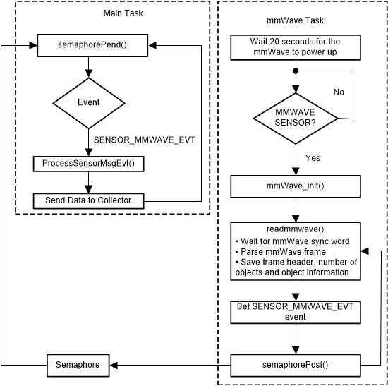
GUID-07E4BEA0-2490-452A-94BB-A65B57C6C60E-low.gif Figure 2-10 Sensor Node Software Flowchart

Each sensor packet includes 4 bytes of the frame number, 4 bytes of the number of objects detected, and 12 bytes of tracking information for each object.

The tracking information for each object is 12 bytes which include 4 bytes track ID, 4 bytes target position in the X dimension, and 4 bytes target position in the Y dimension.

/*!
 mmWave Object Field
 */
typedef struct _Smsgs_objtrackingfield_t
{
    uint32_t tid;
    uint32_t posx;
    uint32_t posy;
} Smsgs_objtrackingfield_t;
/*!
 mmWave Sensor Field
 */
typedef struct _Smsgs_mmwavesensorfield_t
{
    /*! mmWave frame number */
    uint32_t frame_number;
    /*! Number of objects detected */
    uint16_t num_objs;
    /*! Tracking information for each object */
    Smsgs_objtrackingfield_t objInfo[SMSGS_SENSOR_MMWAVE_MAX_OBJ];
} Smsgs_mmwaveSensorField_t;