TIDUF26 june 2023 BQ24072 , LMR36520 , TLV62568 , TPS2116
- 1
- Description
- Resources
- Features
- Applications
- 6
- 1System Description
- 2System Overview
-
3Hardware, Software, Testing Requirements,
and Test Results
- 3.1 Hardware Requirements
- 3.2 Test Setup
- 3.3 Test Results
- 4Design and Documentation Support
- 5About the Author
3.2 Test Setup
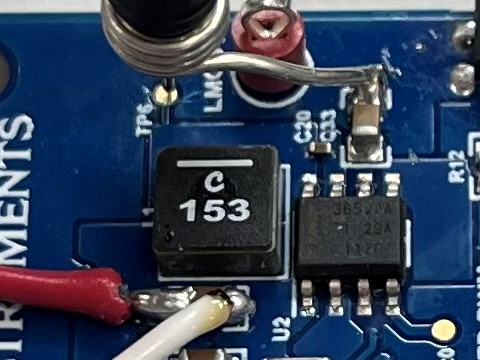
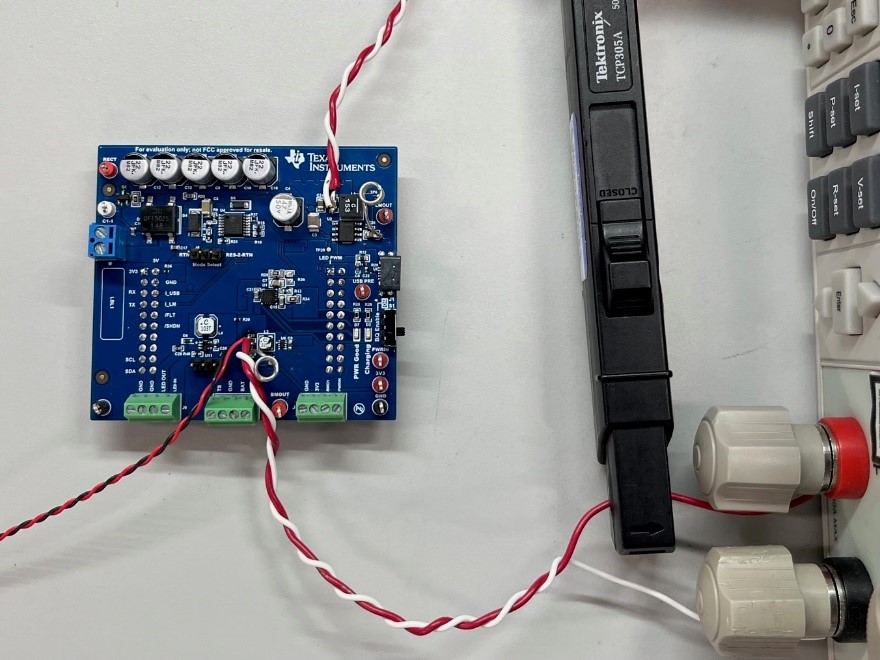
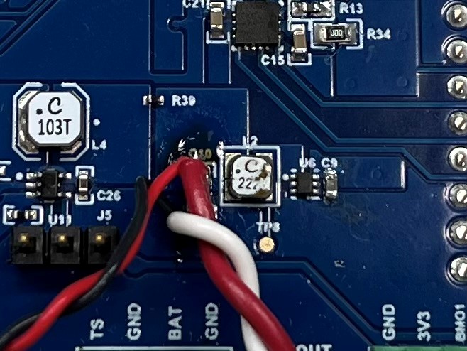
Several test points are made available for each process on the PCB. However, when performing ripple, transient, and efficiency tests, do not use the break out test points due to parasitic noise. Instead, measure the output, input, or other point of interest as close to the IC pins as possible. An example of a transient test setup is shown in Figure 3-1 that uses a barrel wire to GND technique and the current-carrying wires are soldered directly onto the output capacitor of the DC-DC being tested. These current-carrying wires are connected directly to a programmable electronic load and the current is measured through a current probe as shown in Figure 3-2. When performing efficiency plots, separate wires from the current-carrying wires must be used, as shown in Figure 3-3 to avoid inaccurate measurements due to line voltage drops.
 Figure 3-1 Soldered Output Wires and
Scope Probe and Barrel Test Setup
 Figure 3-2 Current Probe and Electronic
Load Test Setup
 Figure 3-3 Separate Sensing and Current
Carrying Wires Test Setup