SLUSF37 December 2022 BQ34Z100-R2
PRODUCTION DATA
- 1 Features
- 2 Applications
- 3 Description
- 4 Revision History
- 5 Pin Configuration and Functions
-
6 Specifications
- 6.1 Absolute Maximum Ratings
- 6.2 ESD Ratings
- 6.3 Recommended Operating Conditions
- 6.4 Thermal Information
- 6.5 Electrical Characteristics: Power-On Reset
- 6.6 Electrical Characteristics: LDO Regulator
- 6.7 Electrical Characteristics: Internal Temperature Sensor Characteristics
- 6.8 Electrical Characteristics: Low-Frequency Oscillator
- 6.9 Electrical Characteristics: High-Frequency Oscillator
- 6.10 Electrical Characteristics: Integrating ADC (Coulomb Counter) Characteristics
- 6.11 Electrical Characteristics: ADC (Temperature and Cell Measurement) Characteristics
- 6.12 Electrical Characteristics: Data Flash Memory Characteristics
- 6.13 Timing Requirements: HDQ Communication
- 6.14 Timing Requirements: I2C-Compatible Interface
- 6.15 Typical Characteristics
- 7 Functional Block Diagram
-
8 Application and Implementation
- 8.1 Application Information
- 8.2
Typical Applications
- 8.2.1 Design Requirements
- 8.2.2
Detailed Design Procedure
- 8.2.2.1
Step-by-Step Design Procedure
- 8.2.2.1.1 STEP 1: Review and Modify the Data Flash Configuration Data.
- 8.2.2.1.2 STEP 2: Review and Modify the Data Flash Configuration Registers.
- 8.2.2.1.3 STEP 3: Design and Configure the Voltage Divider.
- 8.2.2.1.4 STEP 4: Determine the Sense Resistor Value.
- 8.2.2.1.5 STEP 5: Review and Modify the Data Flash Gas Gauging Configuration, Data, and State.
- 8.2.2.1.6 STEP 6: Determine and Program the Chemical ID.
- 8.2.2.1.7 STEP 7: Calibrate.
- 8.2.2.1.8 STEP 8: Run an Optimization Cycle.
- 8.2.2.1
Step-by-Step Design Procedure
- 9 Power Supply Recommendations
- 10Layout
- 11Device and Documentation Support
- 12Mechanical, Packaging, and Orderable Information
Package Options
Mechanical Data (Package|Pins)
- PW|14
Thermal pad, mechanical data (Package|Pins)
Orderable Information
8.2 Typical Applications
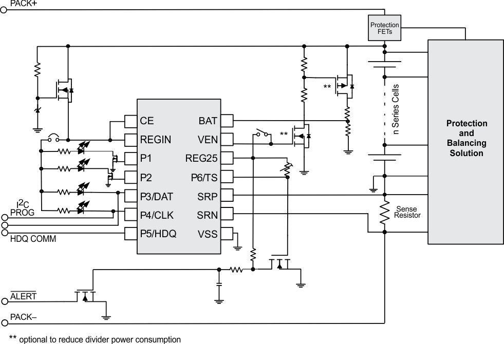
Figure 8-1 is a simplified diagram of the main features of the BQ34Z100-R2. Specific implementations detailing the main configuration options are shown later in this section.
 Figure 8-1 BQ34Z100-R2 Simplified Implementation
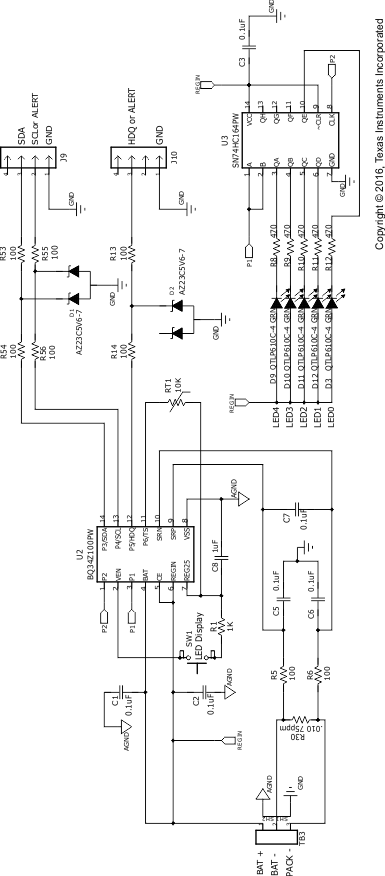
The BQ34Z100-R2 can be used to provide a single Li-ion cell gas gauge with a 5-bar LED display.
 Figure 8-2 1-Cell Li-ion and 5-LED
Display
Figure 8-2 1-Cell Li-ion and 5-LED
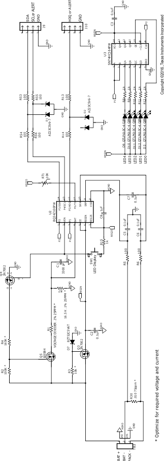
DisplayThe BQ34Z100-R2 can also be used to provide a gas gauge for a multi-cell Li-ion battery with a 5-bar LED display.
 Figure 8-3 Multi-Cell and 5-LED
Display
Figure 8-3 Multi-Cell and 5-LED
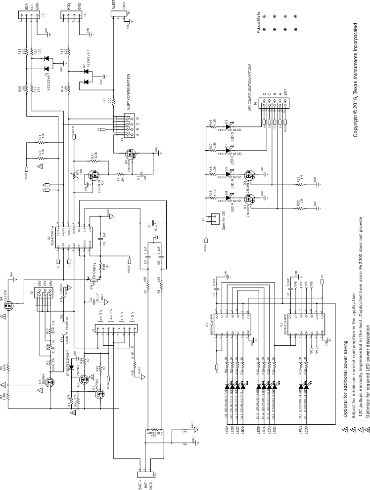
DisplayFigure 8-4 shows the BQ34Z100-R2 full features enabled.
 Figure 8-4 Full-Featured Evaluation Module EVM