SLRS008D September 1986 – January 2016 L293 , L293D
PRODUCTION DATA.
- 1 Features
- 2 Applications
- 3 Description
- 4 Revision History
- 5 Pin Configuration and Functions
- 6 Specifications
- 7 Parameter Measurement Information
- 8 Detailed Description
- 9 Application and Implementation
- 10Power Supply Recommendations
- 11Layout
- 12Device and Documentation Support
- 13Mechanical, Packaging, and Orderable Information
Package Options
Mechanical Data (Package|Pins)
- NE|16
Thermal pad, mechanical data (Package|Pins)
Orderable Information
9 Application and Implementation
NOTE
Information in the following applications sections is not part of the TI component specification, and TI does not warrant its accuracy or completeness. TI’s customers are responsible for determining suitability of components for their purposes. Customers should validate and test their design implementation to confirm system functionality.
9.1 Application Information
A typical application for the L293 device is driving a two-phase motor. Below is an example schematic displaying how to properly connect a two-phase motor to the L293 device.
Provide a 5-V supply to VCC1 and valid logic input levels to data and enable inputs. VCC2 must be connected to a power supply capable of supplying the needed current and voltage demand for the loads connected to the outputs.
9.2 Typical Application
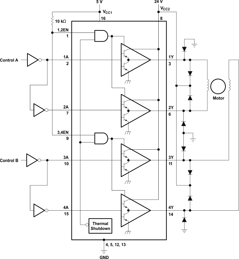 Figure 6. Two-Phase Motor Driver (L293)
9.2.1 Design Requirements
The design techniques in the application above as well as the applications below should fall within the following design requirements.
- VCC1 should fall within the limits described in the Recommended Operating Conditions.
- VCC2 should fall within the limits described in the Recommended Operating Conditions.
- The current per channel should not exceed 1 A for the L293 (600mA for the L293D).
9.2.2 Detailed Design Procedure
When designing with the L293 or L293D, careful consideration should be made to ensure the device does not exceed the operating temperature of the device. Proper heatsinking will allow for operation over a larger range of current per channel. Refer to the Power Supply Recommendations as well as the Layout Example.
9.2.3 Application Curve
Refer to Power Supply Recommendations for additional information with regards to appropriate power dissipation. Figure 7 describes thermal dissipation based on Figure 14.
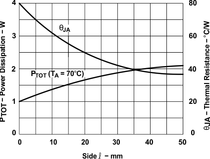 Figure 7. Maximum Power and Junction vs Thermal Resistance
9.3 System Examples
9.3.1 L293D as a Two-Phase Motor Driver
Figure 8 below depicts a typical setup for using the L293D as a two-phase motor driver. Refer to the Recommended Operating Conditions when considering the appropriate input high and input low voltage levels to enable each channel of the device.
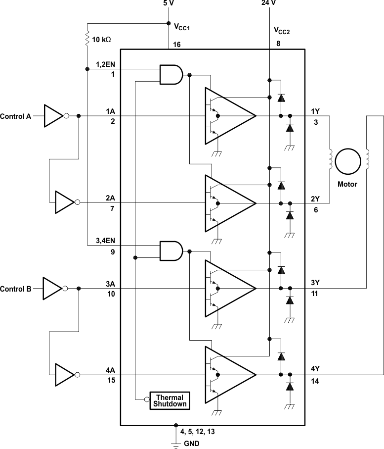 Figure 8. Two-Phase Motor Driver (L293D)
9.3.2 DC Motor Controls
Figure 9 and Figure 10 below depict a typical setup for using the L293 device as a controller for DC motors. Note that the L293 device can be used as a simple driver for a motor to turn on and off in one direction, and can also be used to drive a motor in both directions. Refer to the function tables below to understand unidirectional vs bidirectional motor control. Refer to the Recommended Operating Conditions when considering the appropriate input high and input low voltage levels to enable each channel of the device.
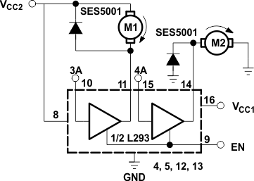
Table 2. Unidirectional DC Motor Control
| EN | 3A | M1(1) | 4A | M2 |
|---|---|---|---|---|
| H | H | Fast motor stop | H | Run |
| H | L | run | L | Fast motor stop |
| L | X | Free-running motor stop | X | Free-running motor stop |
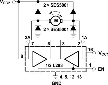 Figure 10. Bidirectional DC Motor Control
Table 3. Bidrectional DC Motor Control
| EN | 1A | 2A | FUNCTION(1) | |
|---|---|---|---|---|
| H | L | H | Turn right | |
| H | H | L | Turn left | |
| H | L | L | Fast motor stop | |
| H | H | H | Fast motor stop | |
| L | X | X | Free-running motor stop | |
9.3.3 Bipolar Stepping-Motor Control
Figure 11 below depicts a typical setup for using the L293D as a two-phase motor driver. Refer to the Recommended Operating Conditions when considering the appropriate input high and input low voltage levels to enable each channel of the device.
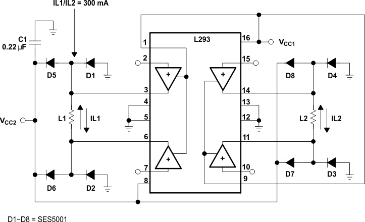 Figure 11. Bipolar Stepping-Motor Control