SNIS160E May 1999 – February 2015 LM135 , LM135A , LM235 , LM235A , LM335 , LM335A
PRODUCTION DATA.
- 1 Features
- 2 Applications
- 3 Description
- 4 Revision History
- 5 Pin Configuration and Functions
- 6 Specifications
- 7 Detailed Description
- 8 Application and Implementation
- 9 Power Supply Recommendations
- 10Layout
- 11Device and Documentation Support
- 12Mechanical, Packaging, and Orderable Information
Package Options
Mechanical Data (Package|Pins)
- NDV|3
Thermal pad, mechanical data (Package|Pins)
Orderable Information
10 Layout
10.1 Layout Guidelines
The LM135 is applied easily in the same way as other integrated-circuit temperature sensors. Glue or cement the device to a surface and the temperature should be within about 0.01°C of the surface temperature.
Efficient temperature transfer assumes that the ambient air temperature is almost the same as the surface temperature where the LM135 leads are attached. If there is a great difference between the air temperature and the surface temperature, the actual temperature of the LM135 die would be at an intermediate temperature between the two temperatures. For example, the TO-92 plastic package, where the copper leads are the principal thermal path to carry heat into the device, can be greatly affected by airflow. The temperature sensed by the TO92 package could greatly depend on velocity of the airflow as well.
To lessen the affect of airflow, ensure that the wiring to the LM135 (leads and wires connected to the leads) is held at the same temperature as the surface temperature that is targeted for measurement. To insure that the temperature of the LM135 die is not affected by the air temperature, mechanically connect the LM135 leads with a bead of epoxy to the surface being measured. If air temperature is targeted for measurement ensure that the PCB surface temperature is close to the air temperature. Keep the LM135 away from offending PCB heat sources such as power regulators. One method commonly used for thermal isolation is to route a thermal well as shown in Figure 33 with the smallest possible geometry traces connecting back to rest of the PCB.
10.2 Layout Example
 Figure 33. Layout Example
10.3 Waterproofing Sensors
Meltable inner-core, heat-shrinkable tubing, such as manufactured by Raychem, can be used to make low-cost waterproof sensors. The LM335 is inserted into the tubing about 0.5 inches from the end and the tubing heated above the melting point of the core. The unfilled 0.5-inch end melts and provides a seal over the device.
10.4 Mounting the Sensor at the End of a Cable
The main error due to a long wire is caused by the voltage drop across that wire caused by the reverse current biasing the LM135 on. Table 2 shows the wire AWG and the length of wire that would cause 1°C error.
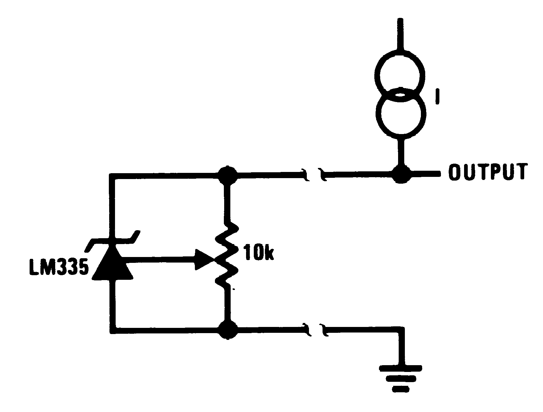 Figure 34. Cable Connected Temperature Sensor
Table 2. Wire Length for 1°C Error Due to Wire Drop
| IR = 1 mA | IR = 0.5 mA(1) | |
|---|---|---|
| AWG | FEET | FEET |
| 14 | 4000 | 8000 |
| 16 | 2500 | 5000 |
| 18 | 1600 | 3200 |
| 20 | 1000 | 2000 |
| 22 | 625 | 1250 |
| 24 | 400 | 800 |